INSTALLATION
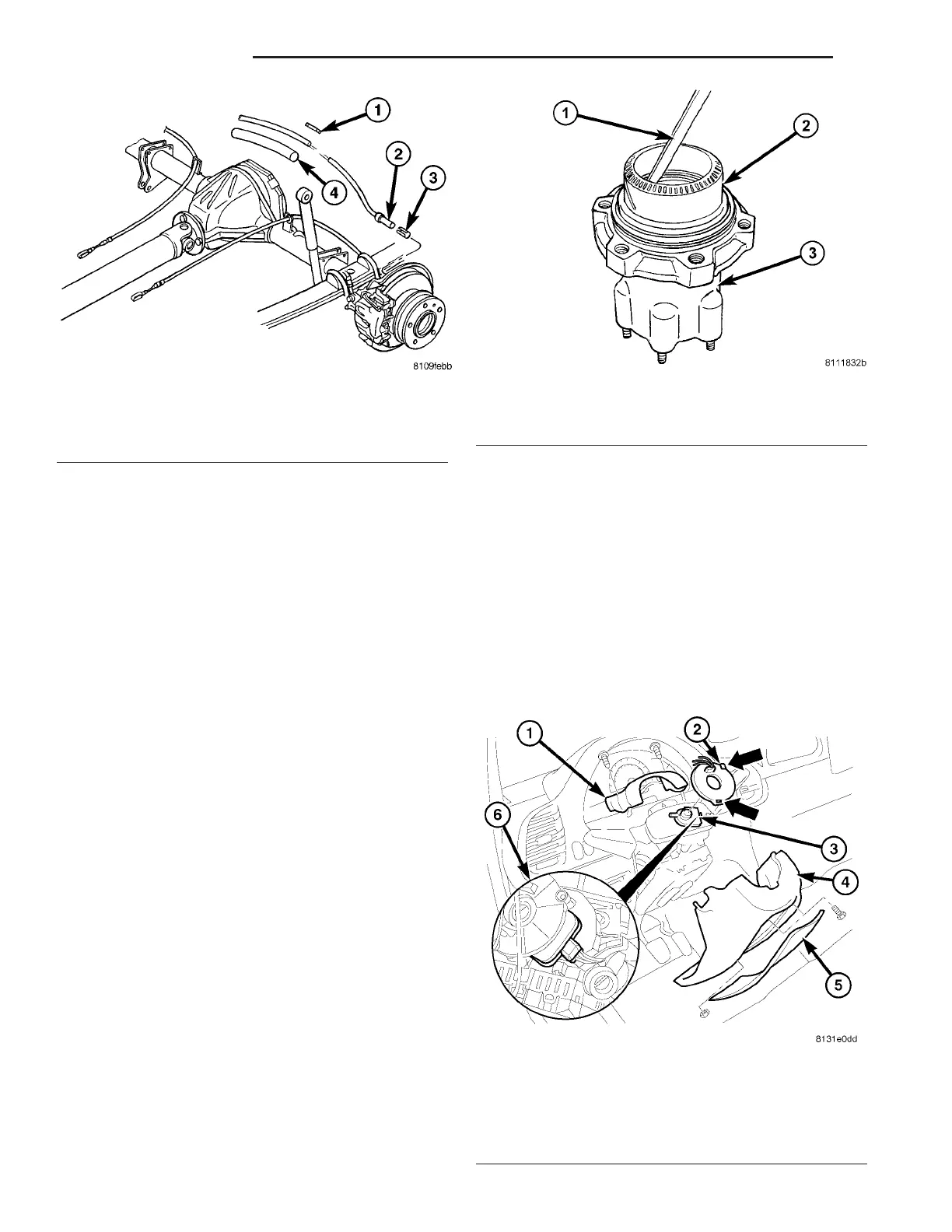
(1) Connect separa te wheel speed sensor cables
with shrink-fit sleeves and shrink-fit t ubin g (F ig. 3).
On l y d o t h i s s t e p i f rep l a c ing t h e s ens o r.
(2) In st all the clamping bushing in to the knuckle
(Fig. 3) On ly d o t h i s s t e p i f re p l a c ing t h e s ens o r
or the clamping bushing was damaged.
(3) In st all th e wh eel speed sensor all t he way into
the axle tu be, the wheel speed sen sor will self adjust
when th e veh icle is moved (Fig. 3).
(4) In st all the rear wh eels.
(5) Lower th e vehicle.
TONE WHEEL
REMOVAL
(1) Remove t he h ub/bea ring a ssem bly (DRW)
(Refer to 3 - DIFFERENTIAL & DRIVELINE/RE AR
AXLE/AXLE BEARINGS - RE MOVAL).
(2) In sert a hooked prybar between the hub/bear-
ing an d the inside of the tone wheel an d pry upwa rds
slightly and work your wa y arou nd th e t one wheel
until the wheel is loose (Fig. 4).
(3) Remove the tone wheel.
INSTALLATION
(1) In st all the tone wh eel t o the hu b/bear ing wit h
a thin bead of silicone around the ton e wheel.
(2) Tap t he ton e wheel down with a soft hammer
until seated.
(3) In st all the hub/bearing (DRW) (Refer to 3 -
DIFFERE NTIAL & DRIVELINE/RE AR AXLE/AXLE
BEARINGS - INSTALLATION).
ST EERI N G AN GLE SEN SOR
DESCRIPTION
Fig. 3 REAR WHEEL SPEED SENSORS
1 - SHRINK-FIT SLEEVE
2 - SPEED SENSOR
3 - CLAMPING BUSHING
4 - SHRINK TUBE
Fig. 4 TONE WHEEL REMOVAL
1 - HOOKED PRYBAR
2 - TONE WHEEL
3 - HUB/BEARING ASSEMBLY
Fig. 5 STEERING ANGLE SENSOR
1 - UPPER STEERING COLUMN COVER
2 - CLOCKSPRING
3 - STEERING ANGLE SENSOR
4 - LOWER STEERING COLUMN COVER
5 - FRONT COVER
6 - STEERING ANGLE SENSOR ELECTRICAL CONNECTION
5-32 BRAKES-ABS VA