The Steer ing Angle Sensor is used t o mea su re rat e/
speed an d direct ion of t he st eerin g wheel. This sen-
sor h as 4 wires 12V, ground and 2 CAN Bus cir cuits.
This sensor is wired directly to the CAN Bus. This
sensor has to be programmed u sing t he DRB III!
(Fig. 5).
REMOVAL
(1) Disconn ect the batt ery.
(2) Remove the a irba g (Refer t o 8 - ELECTRICAL/
RESTRAINTS/AIRBAG CONTROL MODULE -
REMOVAL).
(3) Remove the steer ing wh eel (Refer t o 19 -
STEERING/COLUMN/STEE RING WHEEL -
REMOVAL).
(4) Remove the front cover (Fig. 6).
(5) Remove the upper and lower steering column
covers (F ig. 6).
(6) Remove the clockspring (Refer to8-ELECTRI-
CAL/RESTRAINTS/CLOCKSPRING - RE MOVAL)
(Fig. 6).
(7) Disconn ect the electrical connector from th e
st eering a ngle sensor (Fig. 6).
(8) Remove the st eering a ngle sensor (Fig. 6).
INSTALLATION
NOTE: The installation position of the steering
angle sensor must have the plug connection at the
bottom (Fig. 6).
(1) In st all t he steer ing a ngle sensor to the column
(Fig. 6).
(2) Reconnect the elect rical conn ector to the steer-
ing angle sen sor (Fig. 6).
(3) In st all the clockspring (Refer to8-ELECTRI-
CAL/RESTRAINTS/CLOCKSPRING - INSTALLA-
TION) (Fig. 6).
(4) In st all the u pper an d lower steer ing colum n
covers (F ig. 6).
(5) In st all the front cover (Fig. 6).
(6) In st all the st eering wheel (Refer to 19 -
STEERING/COLUMN/STEE RING WHEEL -
INSTALLATION).
(7) In st all the airbag (Refer to 8 - ELE CTRICAL/
RESTRAINTS/AIRBAG CONTROL MODULE -
INSTALLATION).
(8) Reconnect t he battery.
(9) Recalibrate the steer ing angle sen sor using the
sca n tool.
LAT ERAL ACCELERAT I ON
SEN SOR
DESCRIPTION
The Yaw Rate and Lateral Acceleration Sensor is
housed in to one unit (Fig. 7) (ea c h i n d i v id u a l s e n-
sor can not be replaced separately the whole
housing unit must be replaced when servicing).
The sen sor is used to mea su re side to side (Lateral)
motion a nd vehicle rot ational sen sing (how fast the
vehicle is turn ing). This is a 6–wire sen sor with all
six wires con nected t o the ESP/ABS m odu le.
REMOVAL
(1) Disconn ect the batt ery.
(2) Move t he drivers sea t forward a nd upwards.
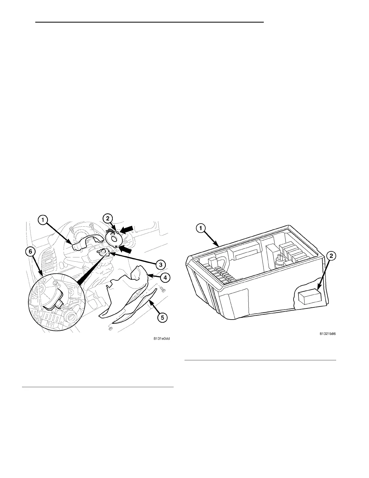
Fig. 6 STEERING ANGLE SENSOR
1 - UPPER STEERING COLUMN COVER
2 - CLOCKSPRING
3 - STEERING ANGLE SENSOR
4 - LOWER STEERING COLUMN COVER
5 - FRONT COVER
6 - STEERING ANGLE SENSOR ELECTRICAL CONNECTION
Fig. 7 YAW/LATERAL ACCELERATION SENSOR
1 - SEAT BOX
2 - YAW RATE/ LATERAL ACCELERATION SENSOR
VA BRAKES - ABS 5 - 33