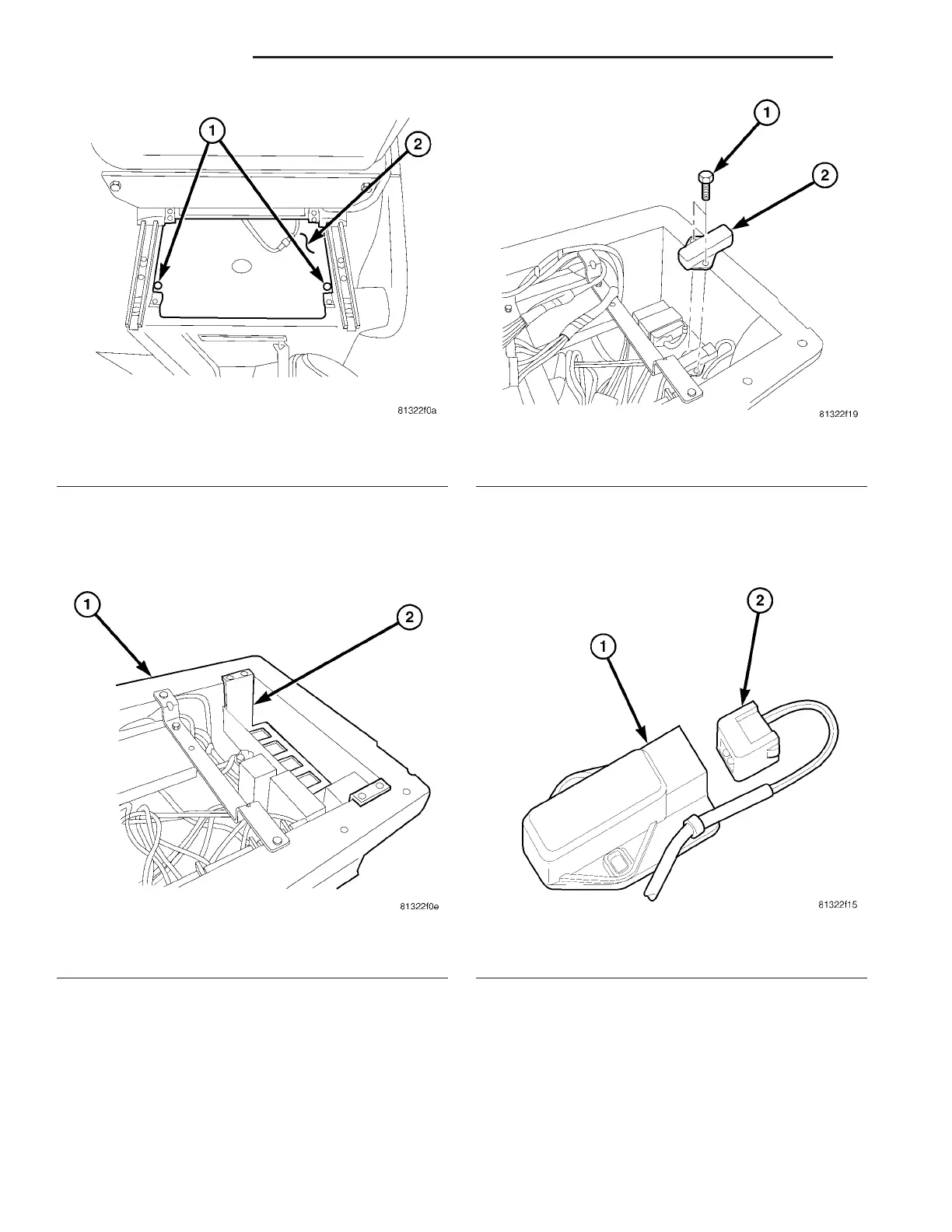
(3) Remove th e cover below the dr iver s sea t (Fig.
8).
(4) Remove the bracket for t he control m odu les
and set aside with the control modules (Fig. 9).
(5) Remove th e screws securing th e Yaw r ate/lat-
eral Accelerat ion Sensor (Fig. 10).
(6) Remove the meta l cover over th e sensor.
(7) Disconn ect the electrical conn ector (Fig. 11).
(8) Remove the Yaw rate/lat eral Accelera tion Sen-
sor.
INSTALLATION
(1) Reconnect the yaw ra te/la tera l accelera tion
sensor elect rica l connector (Fig. 11).
(2) In st all th e yaw rat e/lat eral accelera tion sensor.
(3) In st all the metal cover over top of t he sensor.
(4) In st all the scr ews secur ing t he yaw rate/lateral
accelerat ion sensor (Fig. 10). Tight en to 6 N·m (53
in.lbs).
Fig. 8 COVER
1 - SCREWS
2 - COVER
Fig. 9 CONTROL MODULE BRACKET
1 - SEAT FRAME
2 - BRACKET FOR THE CONTROL MODULES
Fig. 10 SENSOR REMOVE/INSTALL
1 - SCREWS
2 - YAW RATE/LATERAL ACCELERATION SENSOR
Fig. 11 ELECTRICAL CONNECTOR
1 - YAW RATE/ATERAL ACCELERATION SENSOR
2 - ELECTRICAL CONNECTOR
5-34 BRAKES-ABS VA