(5) In st all t he bra cket wit h t he control modules
(Fig. 9).
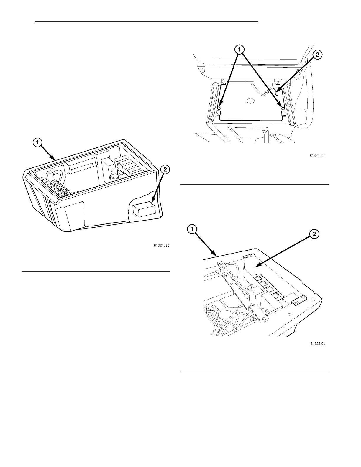
(6) In st all the cover for th e drivers sea t (Fig. 8).
(7) Return the dr iver s seat to n ormal position.
(8) Reconnect t he battery.
(9) Perfor m diagnosis quick check an d road t est
the vehicle.
YAW R ATE SENS OR
DESCRIPTION
The Yaw Rate and Lateral Acceleration Sensor is
housed into one unit (Fig. 12) (ea c h i n d i v id ua l s e n-
sor can not be replaced separately the whole
housing unit must be replaced when servicing).
The sen sor is used to mea su re side to side (Lateral)
motion a nd vehicle rot ational sen sing (how fast the
vehicle is turn ing). This is a 6–wire sen sor with all
six wires con nected t o the ESP/ABS m odu le.
REMOVAL
(1) Disconn ect the batt ery.
(2) Move t he drivers sea t forward a nd upwards.
(3) Remove th e cover below the dr iver s sea t (Fig.
13).
(4) Remove the bracket for t he control m odu les
and set aside with the control modules (Fig. 14).
(5) Remove th e screws securing th e Yaw r ate/lat-
eral Accelerat ion Sensor (Fig. 15).
Fig. 12 YAW/LATERAL ACCELERATION SENSOR
1 - SEAT BOX
2 - YAW RATE/ LATERAL ACCELERATION SENSOR
Fig. 13 COVER
1 - SCREWS
2 - COVER
Fig. 14 CONTROL MODULE BRACKET
1 - SEAT FRAME
2 - BRACKET FOR THE CONTROL MODULES
VA BRAKES - ABS 5 - 35