(6) Remove the meta l cover over th e sensor.
(7) Disconn ect the electrical conn ector (Fig. 16).
(8) Remove the Yaw rate/lat eral Accelera tion Sen-
sor.
INSTALLATION
(1) Reconnect the yaw ra te/la tera l accelera tion
sensor elect rica l connector (Fig. 16).
(2) In st all th e yaw rat e/lat eral accelera tion sensor.
(3) In st all the metal cover over top of t he sensor.
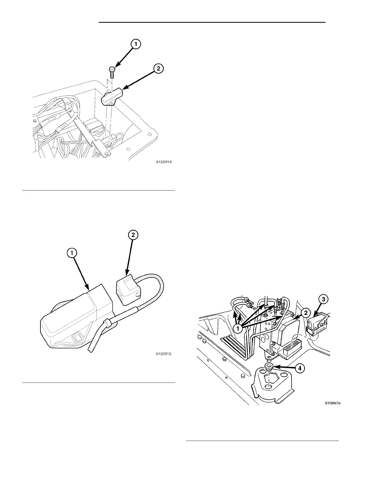
(4) In st all the scr ews secur ing t he yaw rate/lateral
accelerat ion sensor (Fig. 15). Tight en to 6 N·m (53
in.lbs).
(5) In st all t he bra cket wit h t he control modules
(Fig. 14).
(6) In st all the cover for th e drivers sea t (Fig. 13).
(7) Return the dr iver s seat to n ormal position.
(8) Reconnect t he battery.
(9) Perfor m diagnosis quick check an d road t est
the vehicle.
HCU (HYDRAULIC CONTROL
UNIT)
DESCRIPTION
The HCU consists of a valve body, pum p motor, low
pr essu re accumu lators, inlet valves, out let valves a nd
noise a tten uators.
REMOVAL
NOTE: Store the Hydraulic Control Unit in an
upright position only.
(1) Disconn ect the gr ound cable a t t he bat tery.
Th e i g n i t io n s w i t c h m us t b e s w i t c h e d t o t h e o ff
position when disconnecting the battery cable.
(2) Disconn ect the mult iplug fr om the control mod-
ule (Fig. 17).
(3) Disconn ect th e br ake lines fr om th e hydrau lic
control unit (Fig. 17). Mar k t he br ake l ines f or
re ins tallation , a lso se al off th e con n ectio ns an d
lin e s to pre ve nt co ntam in atio n.
(4) Remove t he hydra ulic contr ol unit from the
bracket (Fig. 17).
(5) Check t he ru bber moun ts on the bra cket .
(Replace if n ecessary) (Fig. 17).
Fig. 15 SENSOR REMOVE/INSTALL
1 - SCREWS
2 - YAW RATE/LATERAL ACCELERATION SENSOR
Fig. 16 ELECTRICAL CONNECTOR
1 - YAW RATE/ATERAL ACCELERATION SENSOR
2 - ELECTRICAL CONNECTOR
Fig. 17 HYDRAULIC CONTROL UNIT (ABS)
1 - BRAKE LINES
2 - HCU WITH CONTROL MODULE
3 - ABS/ABD CONTROL MODULE MULTIPLUG
4 - RUBBER SUPPORT
5-36 BRAKES-ABS VA