REM OVAL
REMOVAL
CAUTION: Do not attempt to check belt tension with
a belt tension gauge on vehicles equipped with an
automatic belt tensioner.
NOTE: The belt routing schematics are published
from the latest information available at the time of
publication. If anything differs between these sche-
matics and the Belt Routing Label, use the sche-
matics on Belt Routing Label.This label is located in
the engine compartment.
(1) Remove A/C compressor drive belt (Refer t o 7 -
COOLING/ACCESSORY DRIVE/DRIVE BEL TS -
REMOVAL).
(2) A 3/8 inch squa re hole is provided in the auto-
matic belt tensioner. Attach a 3/8 inch drive-lon g
handle ratchet to this hole (Fig. 3).
(3) Rotat e ratchet a nd tensioner a ssem bly coun ter-
clockwise (a s viewed from front) un til ten sion ha s
been relieved from belt (Fig. 3).
(4) Remove belt from wat er pu mp pulley first.
(5) Remove belt from veh icle.
REMOVAL
(1) Loosen tension adju st er.
(2) Remove A/C compr essor drive belt.
INSTALLATION
INSTALLATION
CAUTION: When installing the accessory drive belt,
the belt must be the correct length and routed cor-
rectly. If not, engine may overheat due to water
pump rotating in wrong direction.
(1) Position drive belt over all pulleys except
water pu mp pulley (F ig. 4).
(2) Attach a 3/8 inch ratchet to tensioner.
(3) Rotat e rat chet and belt ten sioner counterclock-
wise. Pla ce belt over water pump pulley. Let ten-
sioner r otat e back in to place. Remove r atchet . Be
su re belt is proper ly sea ted on all pulleys.
(4) In st all A/C compressor dr ive belt (Refer to 7 -
COOLING/ACCESSORY DRIVE/DRIVE BEL TS -
INSTALLATION).
INSTALLATION
(1) Position A/C compressor drive belt over cran k-
sh aft pulley and A/C compressor pulley.
(2) Tighten drive belt tensioner.
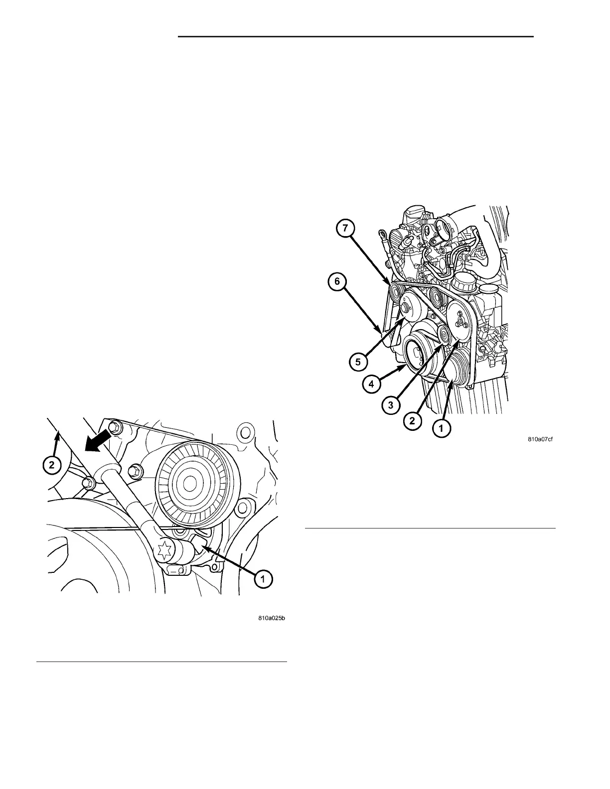
Fig. 3 DRIVE BELT TENSIONER
1 - ACCESSORY DRIVE BELT TENSIONER
2 - RATCHET WRENCH
Fig. 4 ACCESSORY DRIVE BELT ROUTING
1 - A/C COMPRESSOR
2 - POWER STEERING
3 - DRIVE BELT TENSIONER
4 - CRANKSHAFT PULLEY
5 - WATER PUMP PULLEY
6 - GENERATOR
7 - IDLER PULLEY
7 - 8 ACCESSORY DRIVE VA