INSTALLATION
(1) Position th e central timer m odule in the vehicle
(2) Connect th e wire harness connect ors to the
centr al t imer module.
(3) In st all th e screws tha t secur e th e central timer
module. Tighten t he screws securely.
(4) Route the sea t belt latch wire lead thr ough the
hole in th e closeout pan el a nd position the panel
benea th the driver seat cushion
(5) In st all the screws tha t secur e the closeou t
pa nel benea th the driver seat cushion. Tigh ten the
scr ews securely.
(6) Connect the wire har ness connector to the seat
belt latch connector.
(7) Slide the driver seat to ba ck to i t s origina l posi-
tion.
(8) Reconnect t he negat ive batt ery cable.
CON T ROLLER AN T I LOCK
BRAK E
DESCRIPTION
The Contr oler Antilock Bra ke (CAB) is mou nted to
the Hydrau lic Con trol Unit (HCU) an d opera tes t he
ABS system .
REMOVAL
(1) Remove the negat ive ba ttery cable from the
ba t t er y.
(2) Pull up on the CAB h arness connect or release
and rem ove connector.
(3) Remove the CAB mountin g bolts.
(4) Remove the CAB from th e HCU.
INSTALLATION
(1) In st all CAB to the H CU.
(2) In st all mou ntin g bolts. Tight en to 2 N·m (16 in.
lbs.).
(3) In st all the wir ing harness connector t o t he
CAB and push down on the relea se to secu re the con-
nector.
(4) In st all negative batt ery ca ble t o the battery.
EN GI N E CON T ROL M ODU LE
DESCRIPTION
The electr onic con trol module (ECM) is mou nted t o
the left lower dash panel an d consists of an elect ronic
pr inted circuit board which is designed as a milliliter
board assembly fitted on both sides. The routing of
the wiring harn ess con nector at t he ECM connector
are split into in terferin g ca bles and sensitive cables
in order to ach ieve improved electromagnet ic compat-
ibilit y. The smaller wiring harness connect or is used
for the vehicle wiring harness and the larger ha rness
is used for the en gin e wir ing harness. The ECM
st ores engine specific da ta, monitors the connected
sensor and a nalyzes their mea su remen t (Fig. 2).
It s ta sk consists in cont rolling t he following sys-
tems in lin e wit h the a nalysis of the input signa ls:
• Fuel Supply System
• Injected Quantity Cont rol
• Emission Contr ol System
• Ch arge Pr essu re Cont rol
• Cr uise Control
• A/C Compressor Shu t-Off
• Pre-Hea tin g Out pu t Relay for the Glow P lugs
• Vehicle Theft
• Air Bag
• Mon itor s in pu ts/outpu ts, ch ecks plausibility and
st ores fau lts
• Share inform ation with ot her control modules
• Diagnosis
If a sensor should fa il, provided the fault is not
seriou s, the ECM will continu e to operate the engine
in Limp-Home Mode (emergen cy mode) using a
default value for the missin g signa l. The ECM
ensures that, cont inuing to operate the engine will
not cause damage or effect sa fety, otherwise a Engin e
sh ut-off process will be ca rried out (Fig. 3).
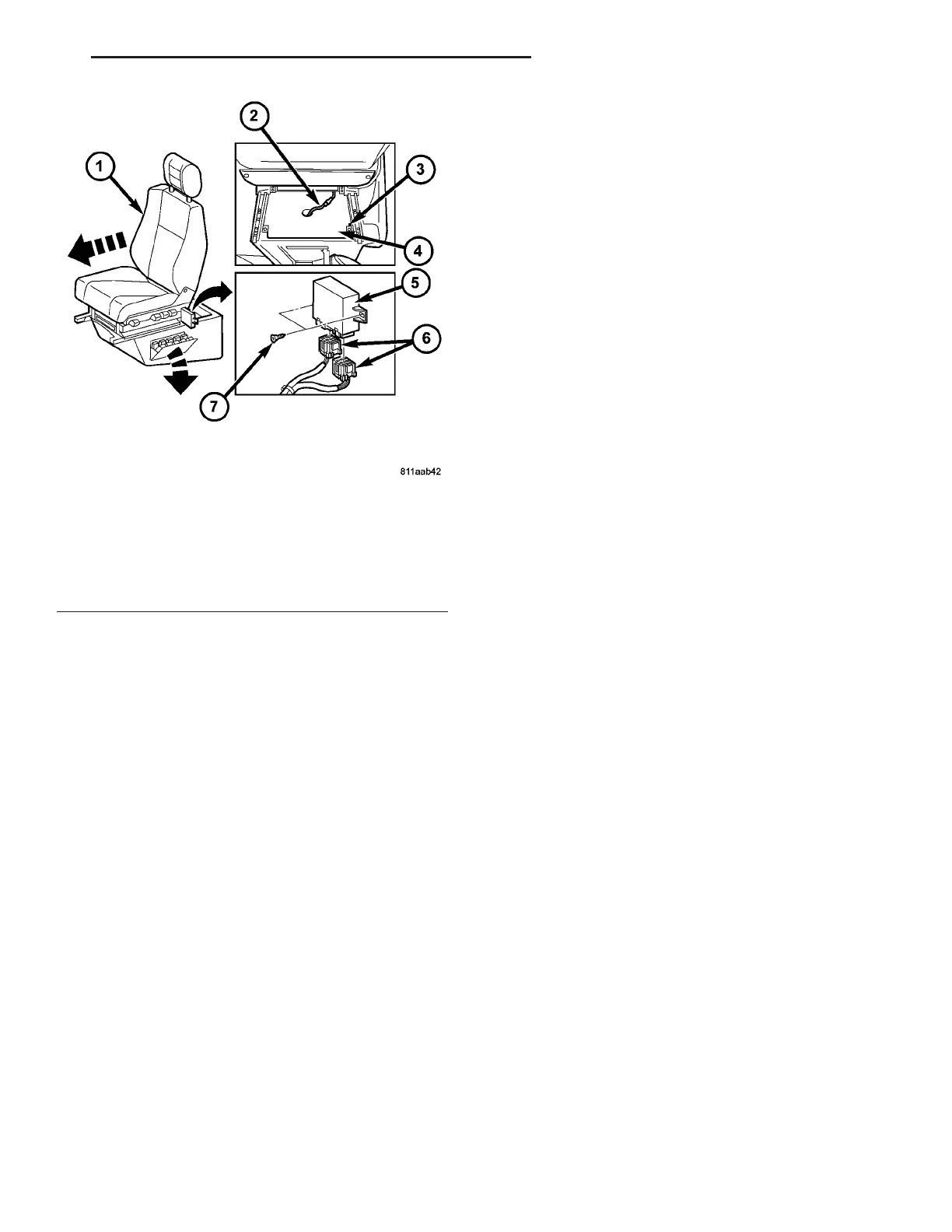
Fig. 1 Central Timer Module
1 - DRIVER SEAT
2 - WIRE HARNESS CONNECTOR
3 - SCREW (2)
4 - CLOSEOUT PANEL
5 - CENTRAL TIMER MODULE
6 - WIRE HARNESS CONNECTOR (2)
7 - SCREW (2)
VA ELECTRONIC CONTROL MODULES 8E - 3