The following oper ation will require a voltm eter
accurate to 1/10 (0.10) volt. Before perfor ming this
test, be certain th at the following procedur es are
accomplished:
• Th e ba tter y is fully-charged a nd test ed. (Refer to
8 - E LECTRICAL/BATTERY SYSTEM/BATTE RY -
STANDARD PROCE DURE ).
• Fully engage the parking brake.
• Place the automatic tr ansmission gearshift selec-
tor lever in the Park position .
• Verify th at all lam ps and a ccessor ies are turned
off.
• Prevent th e engine from startin g.
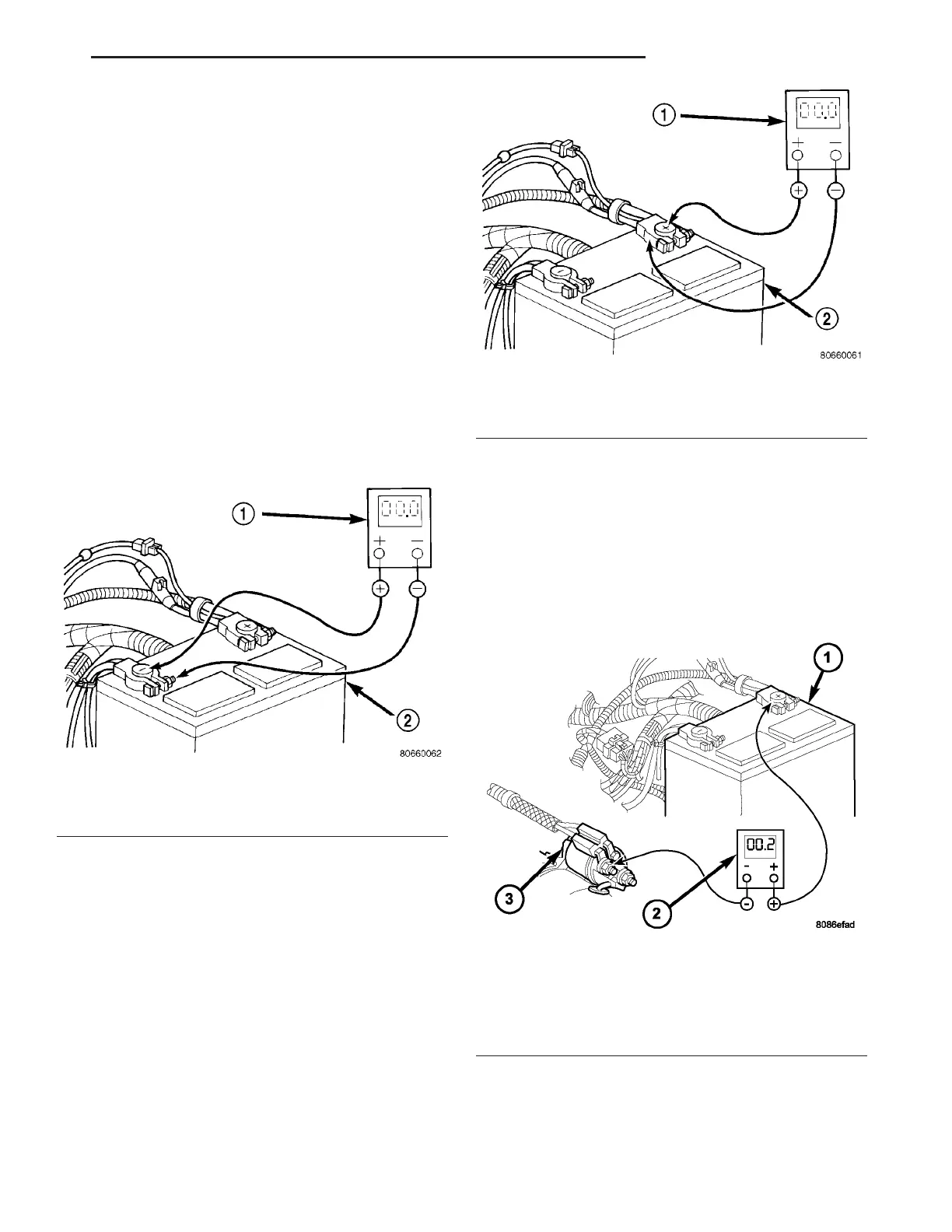
(1) Connect the positive lead of t he voltmeter to
the batt ery n egat ive term ina l post. Connect the neg-
ative lead of the volt meter to the batt ery negative
cable ter min al cla mp (Fig. 9). Rotate a nd h old t he
ign ition switch in th e Start position. Obser ve the
volt meter. If volt age is det ected, correct th e poor con-
nection between t he batt ery n egat ive cable ter minal
clam p a nd the battery negative t erminal post.
(2) Connect the positive lead of t he voltmeter to
the ba tter y positive ter minal post. Connect the nega-
tive lea d of the volt meter to the bat tery positive cable
term inal clamp (Fig. 10). Rot ate and hold the ign ition
switch in the Star t position. Observe th e voltmet er. If
volt age is detected, correct th e poor connection
between the bat tery positive cable ter mina l clamp
and the bat tery positive term inal post.
(3) Connect the volt meter t o measure bet ween the
batt ery posit ive cable termina l clamp and th e st arter
solenoid B(+) terminal stu d (Fig. 11). Rota te and hold
the ignition switch in t he Star t position . Observe the
volt meter. If the reading is a bove 0.2 volt, clean a nd
tighten th e bat tery positive cable eyelet termina l con-
nection a t the sta rter solenoid B(+) term inal st ud.
Repeat the test . If the readin g is still above 0.2 volt ,
repla ce the faulty battery positive ca ble.
(4) Connect the volt meter t o measure bet ween the
batt ery negative cable term inal clamp and a good
clean groun d on the engine block (Fig. 12). Rot ate
and hold the ignition switch in th e Sta rt position.
Observe th e voltmeter. If th e r eadin g is above 0.2
Fig. 9 Test Battery Negative Connection Resistance
- Typical
1 - VOLTMETER
2 - BATTERY
Fig. 10 Test Battery Positive Connection Resistance
- Typical
1 - VOLTMETER
2 - BATTERY
Fig. 11 Test Battery Positive Cable Resistance -
Typical
1 - BATTERY
2 - VOLTMETER
3 - STARTER MOTOR
VA BATTERY SYSTEM 8F - 15