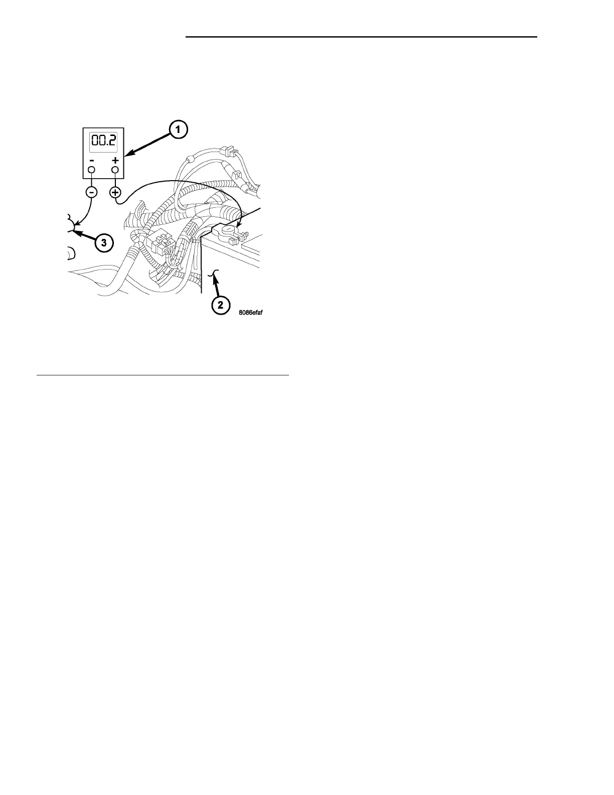
volt , clean an d tighten the bat tery negative cable
eyelet terminal conn ection to the engine block.
Repeat the test . If the readin g is still above 0.2 volt ,
repla ce the faulty battery negative ca ble.
REMOVAL
(1) Turn the ignition switch to the Off posit ion. Be
certa in that all electrical accessories are turned off.
(2) Disconn ect and isolate th e rem ote ba tter y neg-
ative ca ble t erminal.
(3) One at a tim e, trace and discon nect th e bat tery
cable retainin g pushpins, fa st eners and r outing clips
until the cables ar e free fr om the vehicle.
(4) Feed th e batt ery cable assembly ou t of the
vehicle.
INSTALLATION
(1) Position the batt ery cable in th e veh icle.
(2) One at a time, insta ll t he battery cable retain-
ing pushpins, fast eners an d r outing clips until the
cable is installed exactly in t he factory inst alled loca -
tion in the vehicle. Refer to the Wiring Dia gra m sec-
tion of t he service m anua l for reference.
(3) Connect the batt ery n egat ive cable ter minal.
BAT T ERY T RAY
DESCRIPTION
The bat tery is m ounted in a stamped st eel battery
tray located in the left fron t corner of the en gin e
compart ment . The bat tery tray is secured with bolt s
to the left front wheelhouse in ner steel pa nel. A h ole
in the bot tom of the battery tray is fitted with a
formed drain tube. A second hole in the bot tom of the
tray is fitted with a ba tter y tem perat ure sen sor.
OPERATION
The bat tery t ray provides a mounting location and
su pport for t he veh icle ba tter y. The ba tter y tra y sup-
por t support s th e batt ery t ray and provides an
anchor point for the inboard batt ery hold down h ard-
ware. The ba ttery tra y and th e batt ery h old down
hardwa re com bine to secure and stabilize the batt ery
in t he en gin e compar tmen t, which prevents battery
movem ent during vehicle oper ation. Unr estra ined
batt ery movemen t dur ing vehicle operation could
result in damage t o the vehicle, the batt ery or both.
The battery tra y dra in tube direct s spilled water or
electrolyte from a leakin g battery t o the groun d
through anot her hole in the fr ont exten sion of the
left fron t wheelhouse inner pa nel.
REMOVAL
(1) Remove the ba tter y from th e battery tr ay.
(Refer to 8 - ELECTRICAL/BATTE RY SYSTEM/BAT-
TERY - REMOVAL).
(2) Remove the bat tery temperatur e sen sor from
the battery tray. (Refer t o 8 - E LECTRICAL/CHARG-
ING/BATTERY TEMPE RATURE SENSOR -
REMOVAL).
(3) Remove the bolts th at secur e the ba tter y tr ay
to th e bat tery tra y support .
(4) Remove the batt ery tray from th e veh icle.
INSTALLATION
(1) Clean an d inspect th e battery tr ay. (Refer t o 8 -
ELECTRICAL/BATTERY SYSTEM - CLEANING).
(2) Position the batter y tr ay onto the batt ery t ray
su pport.
(3) In st all and t igh ten the bolts t hat secur e the
batt ery tray t o the ba tter y tra y support. Tigh ten the
scr ews to 11.8 N·m (105 in . lbs.).
(4) In st all th e ba tter y temperatur e sensor onto the
batt ery tray. (Refer to 8 - ELECTRICAL/CHARGING/
BATTE RY TEMPERATURE SENSOR - INSTALLA-
TION).
(5) In st all the ba tter y ont o the bat tery tra y. (Refer
to 8 - E LECTRICAL/BATTE RY SYSTEM/BATTERY -
INSTALLATION).
Fig. 12 Test Ground Circuit Resistance - Typical
1 - VOLTMETER
2 - BATTERY
3 - ENGINE GROUND
8F - 16 BAT T ER Y S Y S T EM VA