INSTALLATION
(1) Raise and support vehicle.
(2) Position gen erat or to engine.
(3) In st all 4 generator mount ing bolts (F ig. 1).
Refer to Torque Specificat ions.
(4) Connect field term ina l connector at rear of gen-
erat or.
(5) In st all bat tery output ca ble a nd nut to B+ ter-
minal a t top of gen erat or. Refer to Torqu e Specifica-
tions.
(6) In st all pr otective plastic cover to B+ stu d at
top of genera tor.
(7) Lower vehicle.
CAUTION: Never force a belt over a pulley rim
using a screwdriver. The synthetic fiber of the belt
can be damaged.
CAUTION: When installing a serpentine accessory
drive belt, the belt MUST be routed correctly. The
water pump will be rotating in the wrong direction if
the belt is installed incorrectly, causing the engine
to overheat. Refer to belt routing label in engine
compartment, or refer to Belt Schematics in Cooling
System.
(8) In st all generat or drive belt. Refer to Cooling
System for procedu re.
(9) Connect nega tive bat tery cable.
(10) Check charging system for proper oper ation.
GEN ERAT OR DECOU PLER
PU LLEY
DESCRIPTION
Th e g e ner a to r d ec o up l e r i s us e d o n ly w i t h
certain engines. The decou pler is u sed in pla ce of
the st andar d generat or drive pulley (Fig. 2).
OPERATION
Th e g e ner a to r d ec o up l e r i s us e d o n ly w i t h
certain engines. The decoupler (Fig. 2) is a one-way
clutch designed to help reduce belt ten sion fluctu a-
tion, vibration , reduce fatigue loads, improve belt life,
reduce hubloa ds on components, an d redu ce noise.
Dry opera tion is used (n o gr ease or lubr ican ts). The
decoupler is n ot t empera ture sen sitive and also ha s a
low sen sitivit y to electr ical loa d. The decou pler is a
non-servicea ble item and is to be replaced a s an
assembly.
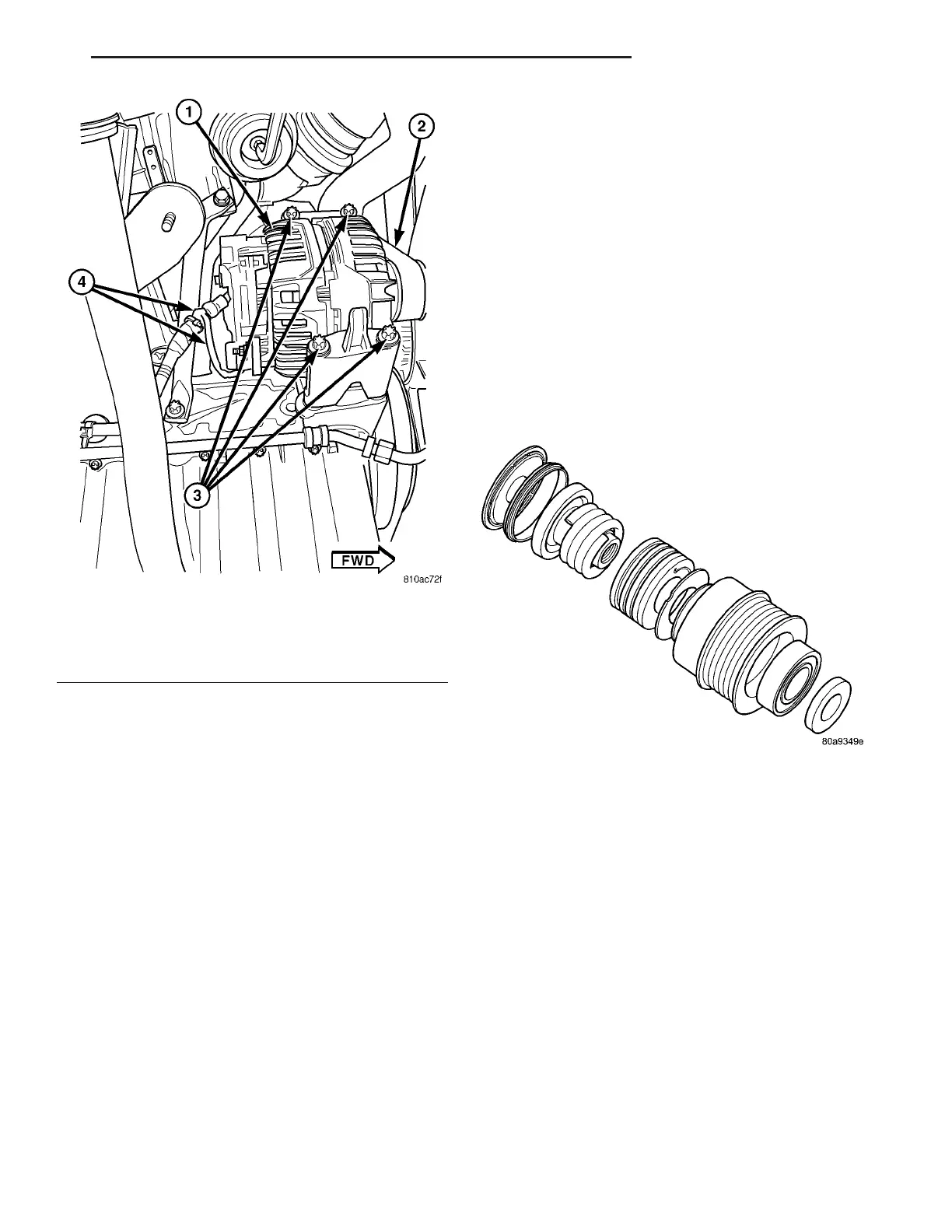
Fig. 1 GENERATOR MOUNTING - 2.7L DIESEL
1 - GENERATOR
2 - DRIVE BELT
3 - MOUNTING BOLTS (4)
4 - GENERATOR WIRING HARNESS
Fig. 2 GENERATOR DECOUPLER PULLEY
VA CHARGING SYSTEM 8F - 19