SPECIAL TOOLS
GEN ERAT OR
DESCRIPTION
The gener ator is belt-driven by the engine using a
serpent ine-t ype drive belt. It is serviced only as a
complet e assembly. If the generat or fails for a ny rea-
son , the entire a ssembly mu st be repla ced.
On cer tain engin es, th e decou pler pu lley m ay be
repla ced sepa rat ely.
OPERATION
As the en ergized rotor begins to rotate within the
generat or, the spinn ing ma gnetic field induces a cur-
rent int o the windings of the stator coil. Once th e
generat or begins producing sufficient curr ent, it also
pr ovides t he cur rent needed to en ergize t he rot or.
The stator windin g connect ions deliver the in du ced
AC current to 3 positive and 3 negative diodes for
rectification. From t he diodes, rectified DC curr ent is
delivered to the veh icle electr ical system through the
generat or batter y terminal.
Although t he gener ator s appear the sa me exter-
nally, differen t generat ors with differen t output r at-
ings ar e used on this vehicle. Be certain tha t the
repla cement genera tor has t he sa me output rating
and par t nu mber as the origin al un it. Refer to Spec-
ifica tions and see Gener ator Ra tin gs for amper age
ratings and part numbers.
Noise em itt ing from the gener ator ma y be caused
by: worn, loose or defective bea rings; a loose or defec-
tive dr ive pulley (decou pler pulley); incorr ect, worn ,
da maged or misadju st ed fan drive belt; loose mount-
ing bolt s; a misa ligned dr ive pu lley or a defective st a-
tor or diode.
An instrumen t pa nel mount ed, ba tter y ch arge indi-
cator lamp is used. When the key is in th e on posi-
tion, the lamp will be illuminated. Th is is done as a
bulb check. If th is lam p r emains illum ina ted while
the engine is ru nning, a Diagn ost ic Trouble Code
(DTC) has been detected for th e char gin g system.
REMOVAL
CAUTION: DISCONNECT NEGATIVE CABLE FROM
BATTERY BEFORE REMOVING BATTERY OUTPUT
WIRE FROM GENERATOR. FAILURE TO DO SO
CAN RESULT IN INJURY.
CAUTION: Never force a belt over a pulley rim
using a screwdriver. The synthetic fiber of the belt
can be damaged.
CAUTION: When installing a serpentine accessory
drive belt, the belt MUST be routed correctly. The
water pump will be rotating in the wrong direction if
the belt is installed incorrectly, causing the engine
to overheat. Refer to belt routing label in engine
compartment, or refer to Belt Schematics in Cooling
System.
(1) Disconn ect and isolate negative batt ery ca ble.
(2) Remove generator drive belt. Refer t o Cooling
System for procedu re.
(3) Raise and support vehicle.
(4) Remove protective plast ic cover from B+ stu d
at top of gener ator.
(5) Remove nut secu ring battery out pu t cable to
B+ t erminal at top of gener ator.
(6) Unplug field ter minal connector at rear of gen-
erat or.
(7) Remove 4 gen erat or mountin g bolts (Torx-style
#12 bit) (Fig. 1).
(8) Remove gener ator from lower side of veh icle.
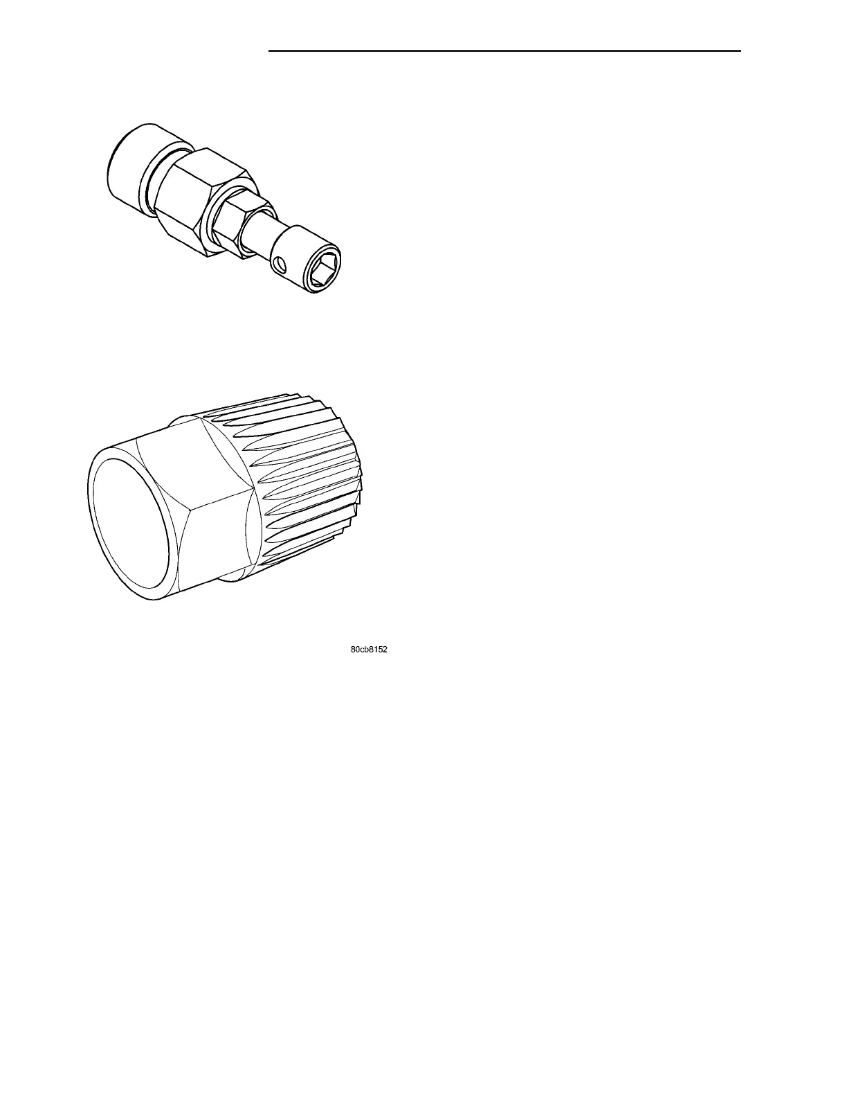
GENERATOR DECOUPLER TOOL #8433
GENERATOR DECOUPLER TOOL #8823
8F - 18 CHARGING SYSTEM VA