Starting System Diagnosis
CONDITION POSSIBLE CAUSE CORRECTION
STARTER DOES NOT
DISENGAGE.
1. Starter motor improp-
erly installed.
1. Refer to Starter Motor Removal and Installation.
Tighten starter mounting hardware to correct torque
specifications.
2. Starter relay faulty. 2. Refer to Starter Relay Diagnosis and Testing. Re-
place starter relay if required.
3. Ignition switch faulty. 3. Refer to Ignition Switch and Key Lock Cylinder. Re-
place ignition switch if required.
4. Starter motor faulty. 4. If all other starting system components and circuits
test OK, replace starter motor.
INSPECTION
For complete starter wiring circu it diagram s, refer
to 8, Wiring Diagram s. Before removing a ny un it
from starting system for repair or dia gnosis, perfor m
the following inspections:
WARNING: ON VEHICLES EQUIPPED WITH AIR-
BAGS, REFER TO 8, PASSIVE RESTRAINT SYS-
TEMS, BEFORE ATTEMPTING ANY STEERING
WHEEL, STEERING COLUMN, OR INSTRUMENT
PANEL COMPONENT DIAGNOSIS OR SERVICE.
FAILURE TO TAKE THE PROPER PRECAUTIONS
COULD RESULT IN ACCIDENTAL AIRBAG DEPLOY-
MENT AND POSSIBLE PERSONAL INJURY.
• Battery - Visually inspect battery for in dica-
tions of ph ysica l dam age and loose or corr oded cable
connect ions. Determ ine sta te-of-cha rge an d cra nking
capacity of ba tter y. Cha rge or replace batt ery if
required. Refer to Battery in 8 , Batte ry.
• Ig n i t io n S wi t c h - Visua lly inspect ign ition
switch for indications of physical dama ge an d loose
or cor roded wire ha rness connect ions. Refer to Ig ni -
tion Sw itch and Key Lock Cylinder.
• P a rk /N e u t ra l P os itio n S w itc h -Visually
inspect pa rk/n eutr al position switch for indications of
ph ysical dam age and loose or corroded wir e ha rness
connect ions. Refer to P ark /N e u tra l P os itio n
Switch in 21, Transmission.
• Starter Relay - Visua lly inspect star ter relay
for indications of physical damage and loose or cor-
roded wir e harness conn ection s.
• Starter Motor - Visua lly inspect st arter motor
for indications of physical damage and loose or cor-
roded wir e harness conn ection s.
• Starter Solenoid - Visually i n spect star ter sole-
noid for indications of physical damage and loose or
corroded wire h arness con nections.
• Wi r i n g - Visually inspect wire ha rnesses for
da mage or corrosion. Repair or replace any fault y
wiring, as required. Refer to 8, Wiring Diagrams.
TESTING
COLD CRANKING TEST
For complete starter wiring circu it diagram s, refer
to 8, Wir ing Diagram s. The battery must be fully-
charged and loa d-t est ed before proceeding. Refer to
Battery in 8 , Battery.
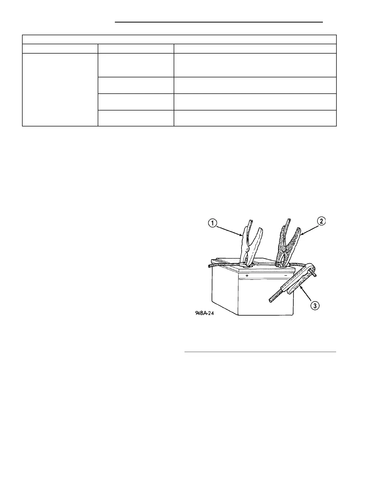
(1) Connect volt-am pere tester t o bat tery ter min als
(Fig. 1). See instructions provided by ma nufacturer of
volt -ampere tester being used.
(2) Fully enga ge parking brake.
(3) Pla ce gearshift selector lever in Par k posit ion.
(4) Verify tha t all lamps and accessories ar e
turned off.
(5) To prevent engine from sta rting, rem ove F uel
Pump Rela y. Th is relay is located in Power Distr ibu-
tion Cen ter (PDC). Refer to label on PDC cover for
rela y loca tion .
WARNING: IF EQUIPPED WITH DIESEL ENGINE,
ATTEMPT TO START ENGINE A FEW TIMES
BEFORE PROCEEDING WITH FOLLOWING STEP.
Fig. 1 VOLTS-AMPS TESTER CONNECTIONS -
TYPICAL
1 - POSITIVE CLAMP
2 - NEGATIVE CLAMP
3 - INDUCTION AMMETER CLAMP
8F - 30 STARTING SYSTEM VA