(6) Rotat e and hold ignit ion switch in St art posi-
tion. Not e cran kin g volta ge an d cu rren t (amper age)
dr aw readin gs shown on volt-ampere t est er.
(a) If voltage r eads below 9.6 volts, refer to
Starter Motor in Dia gnosis a nd Testing. If sta rter
motor is OK, r efer to Engine Diagnosis in 9 ,
Engine for further testing of en gin e. If sta rter
motor is not OK, replace fa ult y starter mot or.
(b) If volta ge rea ds a bove 9.6 volts an d current
(amper age) draw rea ds below specifica tions, refer
to Feed Circuit Test in this section.
(c) If voltage r eads 12.5 volts or grea ter an d
st arter m otor does not t urn, refer t o Co n t ro l Ci r-
cuit Testing in this section .
(d) If volta ge rea ds 12.5 volts or greater an d
st arter mot or turns very slowly, refer to Feed Cir-
cuit Test i n t his section.
NOTE: A cold engine will increase starter current
(amperage) draw reading, and reduce battery volt-
age reading.
FEED CIRCUIT TEST
The sta rter feed circu it test (volt age drop met hod)
will deter mine if ther e is excessive resistan ce in
high-am perage feed circuit. F or complete sta rter wir-
ing circuit diagrams, refer 8, Wiring Diagram s.
When perfor ming these test s, it is import ant to
remember t hat volta ge drop is giving an indication of
resistance between two poin ts at which voltmeter
pr obes are att ached.
Example: When test ing resistan ce of positive ba t-
tery cable, touch volt meter lea ds t o posit ive battery
cable clamp an d cable connect or at st arter solenoid.
If you pr obe posit ive ba ttery terminal post and cable
connect or a t sta rter solen oid, you are r eading com-
bined voltage drop in positive battery cable cla mp-to-
term inal post connect ion and posit ive batt ery cable.
The following oper ation will require a voltm eter
accurate to 1/10 (0.10) volt. Before per forming test s,
be certain th at following procedu res a re accom-
plished:
• Ba tter y is fully-charged a nd load-test ed. Refer t o
Battery in 8 , Battery.
• Fully engage parking brake.
• Place gea rshift selector lever in Par k posit ion.
• Verify th at all lam ps and a ccessor ies are turned
off.
• To pr event engine from st arting, remove Fu el
Pump Rela y. Th is relay is located in Power Distr ibu-
tion Cen ter (PDC). Refer to label on PDC cover for
rela y loca tion .
(1) Connect posit ive lead of voltmeter to negat ive
batt ery cable ter mina l post. Connect negat ive lead of
volt meter to negative batt ery ca ble clamp (Fig. 2).
Rotat e a nd hold ignition switch in Start position .
Observe voltm eter. If voltage is detected, correct poor
contact between ca ble clamp a nd ter minal post.
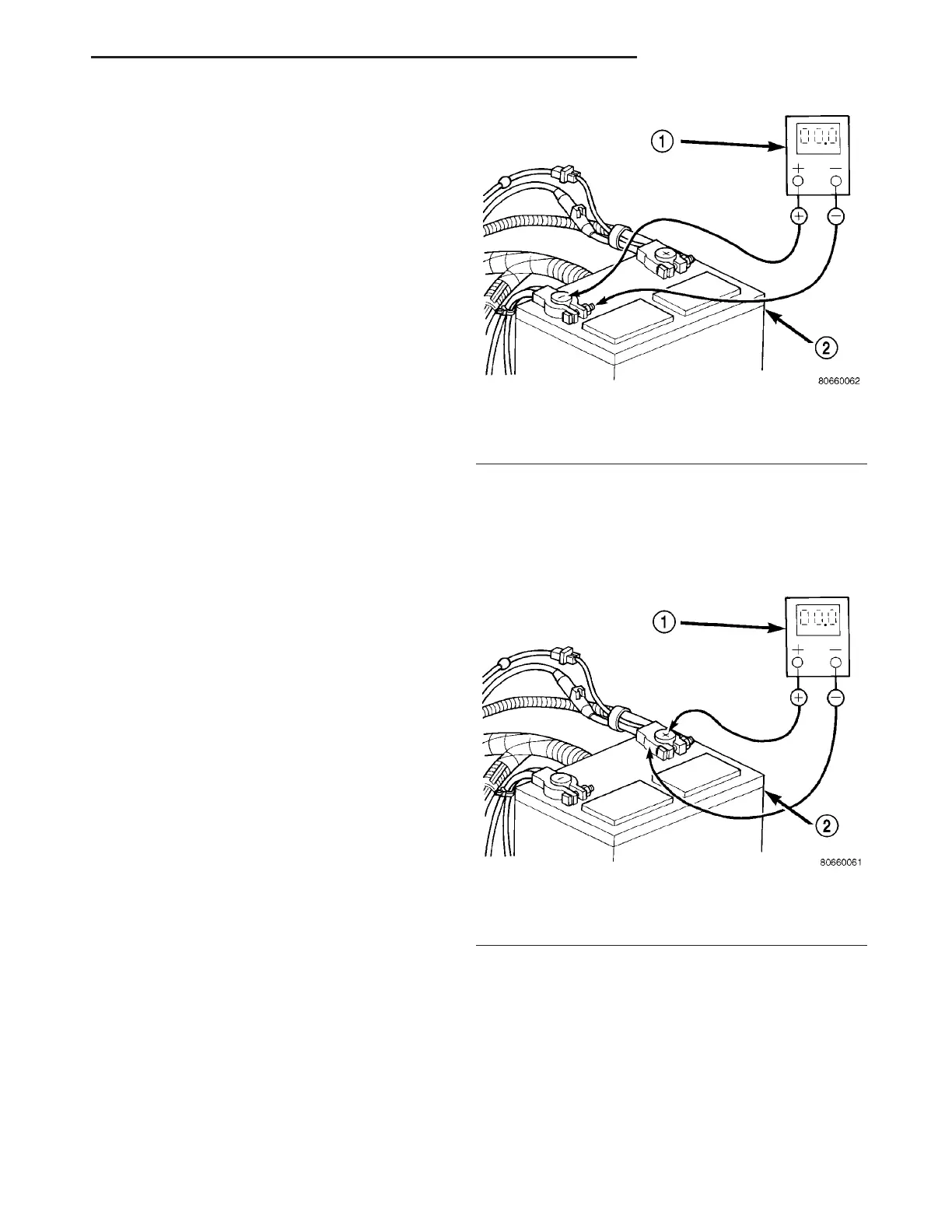
(2) Connect positive lea d of voltmeter to positive
batt ery ter min al post. Conn ect n egat ive lead of volt-
meter to batt ery positive cable clamp (F ig. 3). Rota te
and h old ignit ion swit ch in Sta rt position. Observe
volt meter. If voltage is detected, correct poor conta ct
between cable cla mp and t erminal post.
(3) Connect voltmeter t o measure between ba tter y
positive ter minal post an d starter solenoid batter y
term inal stud (F ig. 4). Rot ate and h old ignition
switch in St art position. Obser ve voltmet er. If r ead-
ing is a bove 0.2 volt, clea n a nd t igh ten batt ery cable
connect ion a t solenoid. Repeat test. If reading is still
above 0.2 volt , replace fau lty positive bat tery cable.
Fig. 2 TEST NEGATIVE BATTERY CABLE
CONNECTION RESISTANCE - TYPICAL
1 - VOLTMETER
2 - BATTERY
Fig. 3 TEST POSITIVE BATTERY CABLE
CONNECTION RESISTANCE - TYPICAL
1 - VOLTMETER
2 - BATTERY
VA STARTING SYSTEM 8F - 31