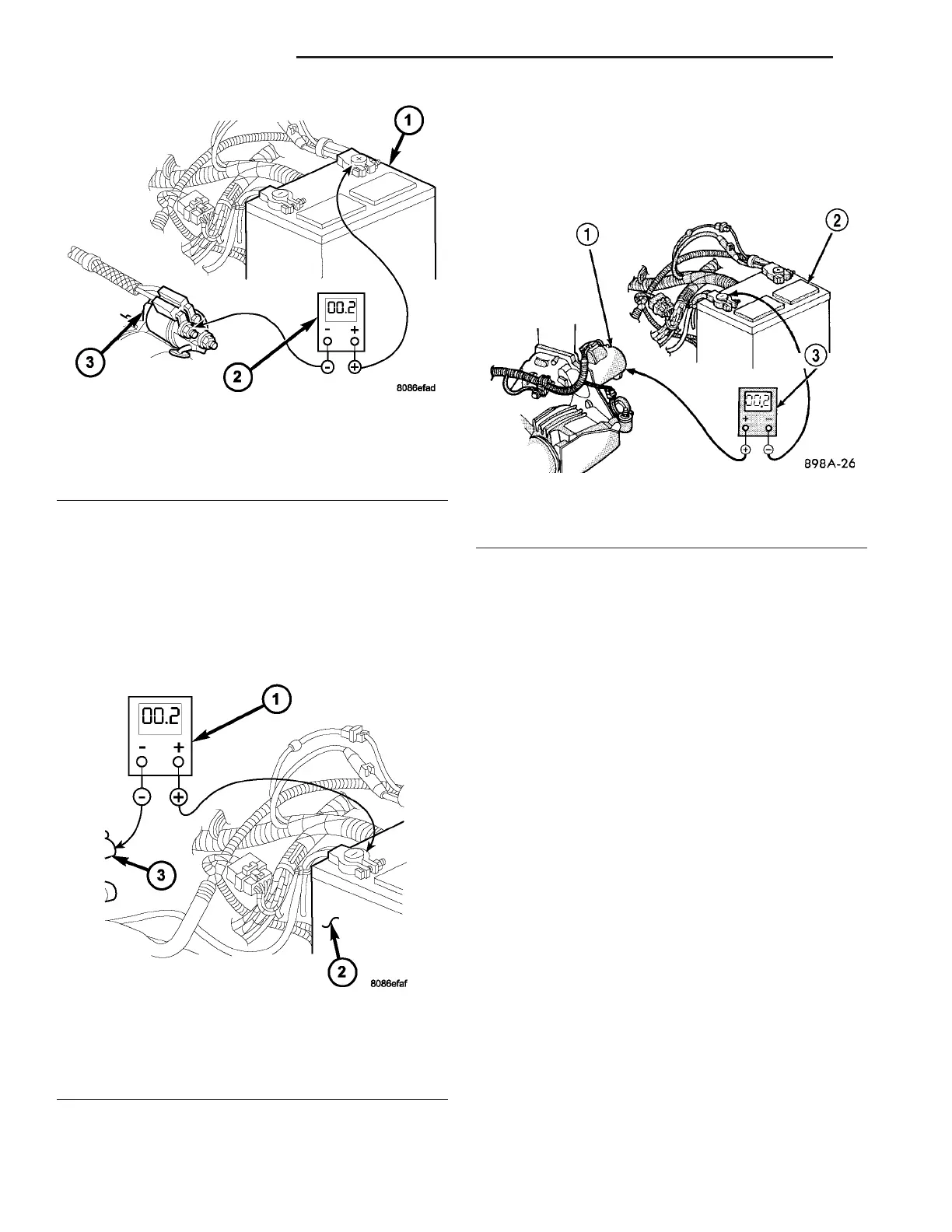
(4) Connect voltmeter to m easur e between nega-
tive battery term inal post and a good clea n ground
on engine block (Fig. 5). Rota te a nd hold ignition
switch in St art position. Obser ve voltmet er. If r ead-
ing is above 0.2 volt , clean and tighten n egat ive bat-
tery cable attachm ent on en gin e block. Repeat test. If
reading is still a bove 0.2 volt , replace faulty nega tive
batt ery cable.
(5) Connect positive lea d of voltmeter to starter
housin g. Connect nega tive lead of voltmeter to n ega-
tive bat tery termina l post (Fig. 6). Rotat e and hold
ign ition switch in Sta rt position. Observe voltmeter.
If reading is above 0.2 volt, correct poor sta rter to
engine block groun d con tact.
If resistance tests detect no feed circuit pr oblems,
refer to Starter Motor in t he Dia gnosis and Testing.
CONTROL CIRCUIT TESTING
The sta rter control circuit components shou ld be
tested in the order in which th ey are listed, as fol-
lows:
• Starter Relay - Refer t o Starter Relay Dia g-
nosis an d Testing.
• Starter Solenoid - Refer to Starter Motor
Diagnosis and Testing.
• Ig n i t io n S w i tc h - Refer to Ig n i t io n S wi tc h
and Key Lock Cylinder
• P a rk /N e u t ra l P os iti o n Sw itc h -Ifequipped
with automa tic t ransmission, r efer to P ark /N e u t ra l
Position Switch in 21, Tra nsmission.
• Wi r e h a r n e s s e s a n d c o n n e c t i o n s - Refer t o 8,
Wiring Diagram s.
Fig. 4 TEST POSITIVE BATTERY CABLE
1 - BATTERY
2 - VOLTMETER
3 - STARTER MOTOR
Fig. 5 TEST GROUND CIRCUIT RESISTANCE -
TYPICAL
1 - VOLTMETER
2 - BATTERY
3 - ENGINE GROUND
Fig. 6 TEST STARTER GROUND - TYPICAL
1 - STARTER MOTOR
2 - BATTERY
3 - VOLTMETER
8F - 32 STARTING SYSTEM VA