INSTALLATION
(1) Raise and support vehicle.
(2) Position sta rter m otor to transmission hou sing.
(3) In st all 2 moun ting bolts. Refer to Torque Spec-
ifica tions.
(4) Lower vehicle.
(5) Connect battery ca ble and solenoid wiring to
solenoid (2 nu ts). Refer to Torque Specifica tions.
(6) Position wiring harn ess t rough an d install
reta ining bolt.
(7) In st all new nylon tie-wraps to wiring trou gh.
(8) Connect nega tive bat tery cable.
START ER M OT OR RELAY
DESCRIPTION
The sta rter relay is a n electromecha nica l device
that swit ches batt ery current to the pull-in coil of th e
st arter solen oid when ign ition switch is turned t o
St art position. Th e star ter relay is loca ted in the
Fuse/Relay Block. The Fuse/Rela y Block is located
under, and to t he left side of th e driver s seat . See
Fuse/Relay Block cover for relay ident ification and
locat ion.
The sta rter relay is an Int erna tional Sta ndards
Orga nization (ISO) relay. Relays conforming to ISO
specifica tions ha ve common physical dimen sions, cur-
rent ca pa cities, ter minal patterns, and t erminal func-
tions.
The starter relay cannot be repaired or adjusted
and, if fau lty or da maged, it must be replaced.
REMOVAL
The star ter relay is loca ted in the Fuse/Relay
Block. Th e F use/Relay Block is loca ted under, a nd t o
the left side of th e dr iver s seat. See Fuse/Rela y Block
cover for rela y identifica tion an d location, or refer to
(Fig. 12).
(1) Remove Fuse/Relay Block cover by pushing
down on two ta bs located at top of cover (Fig. 13).
(2) Remove relay from Fu se/Relay Block.
(3) Check condition of relay termina ls and Fuse/
Relay Block con nector ter min als for dama ge or corr o-
sion. Repa ir if necessary before insta lling relay.
(4) Check for pin h eight (pin height should be th e
sa me for all termina ls within th e Fuse/Relay Block
connect or). Repa ir if necessar y before insta lling
relay.
Fig. 11 WIRING TROUGH - FOR STARTER REMOVAL
(VIEW FROM REAR)
1 - WIRING TROUGH
2 - REAR/LEFT END OF TRANS. BELLHOUSING (VIEW FROM
REAR)
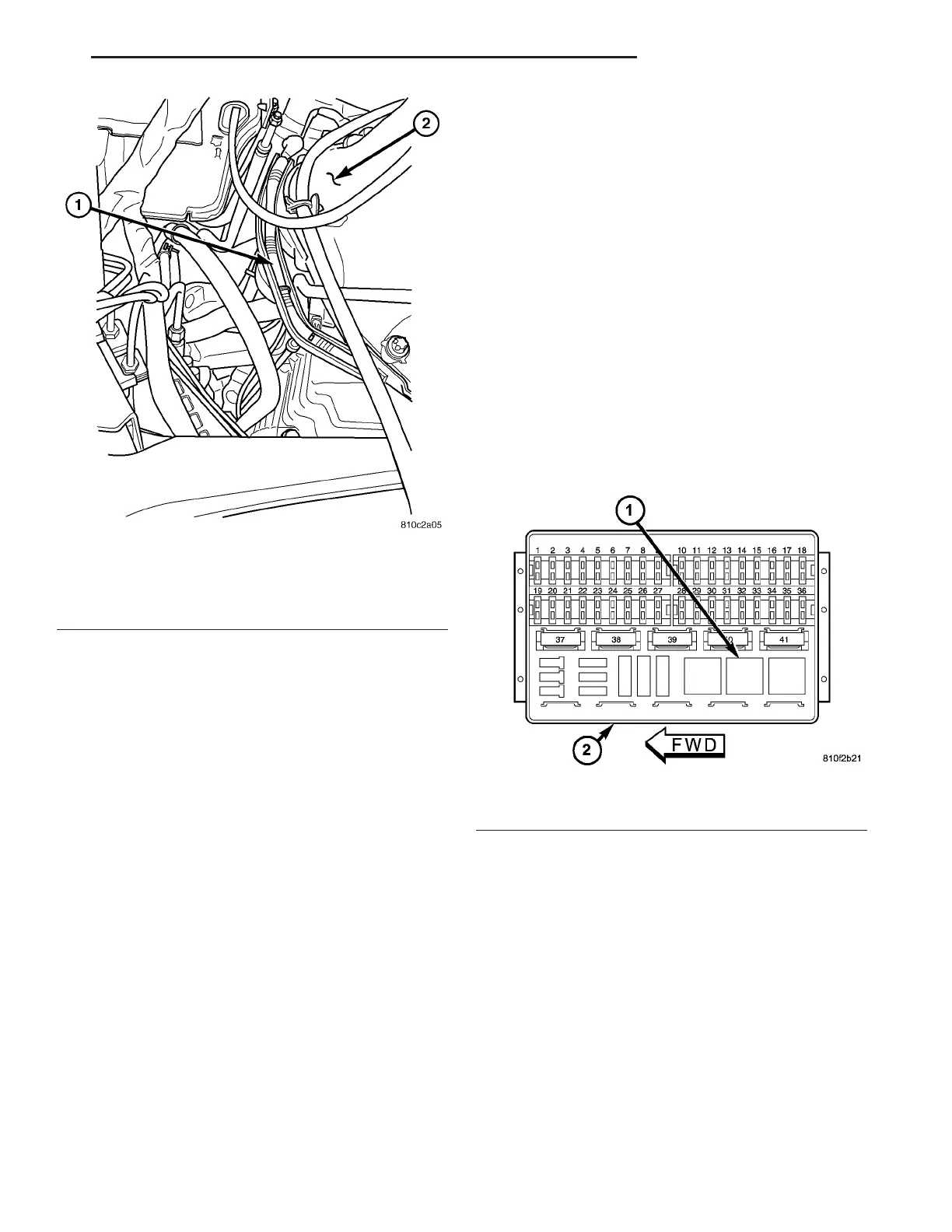
Fig. 12 FUSE / RELAY BLOCK
1 - STARTER RELAY LOCATION
2 - FUSE / RELAY BLOCK
VA STARTING SYSTEM 8F - 35