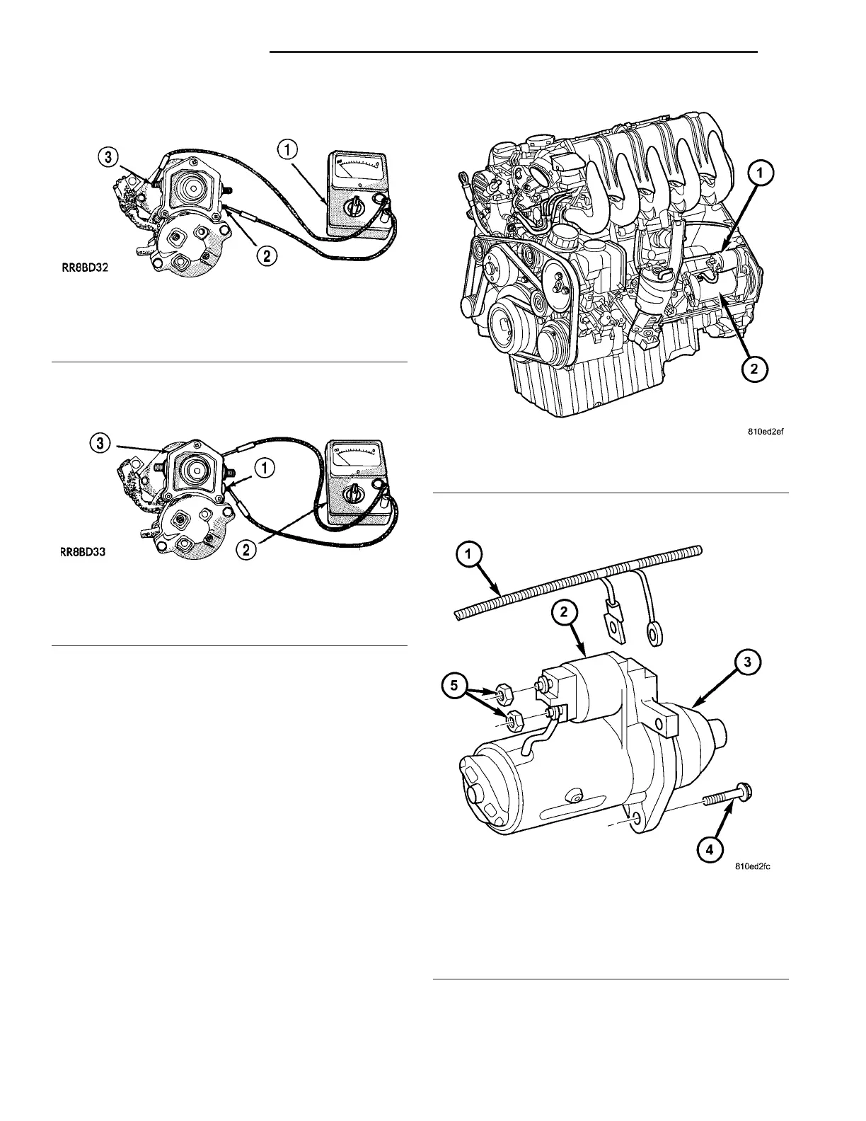
tester (Fig. 7). There shou ld be con tin uity. If OK, go
to Step 4. If not OK, replace fau lty starter m otor
assembly.
(4) Check for continuity between solenoid t erminal
and solenoid ca se (Fig. 8). Ther e sh ould be continuity.
If not OK, replace fa ulty star ter mot or assembly.
REMOVAL
The starter mot or and solen oid a ssembly is locat ed
at the left/r ear side of engine (F ig. 9).
(1) Disconn ect and isolate negative batt ery ca ble.
(2) Working from u nder vehicle hood, rem ove bolt
reta ining wiring trough (Fig. 11) to tran sm ission bell-
housin g.
(3) Working from u nder vehicle hood, cut n eces-
sa ry n ylon ; wiring trou gh t ie-wr aps nea r starter
motor. Temporarily position wiring ha rness t rough
for access to starter.
(4) Working from under vehicle hood, remove 2
st arter solenoid wiring har ness nuts (Fig. 10).
(5) Remove solen oid wir e conn ector from solenoid
st ud, and ba tter y cable from solenoid st ud.
(6) Raise and support vehicle.
(7) Remove 2 star ter mou ntin g bolt s (E14Torx)
(Fig. 10).
(8) Remove starter from tran sm ission bellhous-
ing.
Fig. 7 CONTINUITY BETWEEN SOLENOID AND
FIELD COIL TERMINALS - TYPICAL
1 - OHMMETER
2 - SOLENOID TERMINAL
3 - FIELD COIL TERMINAL
Fig. 8 CONTINUITY BETWEEN SOLENOID
TERMINAL AND CASE - TYPICAL
1 - SOLENOID TERMINAL
2 - OHMMETER
3 - SOLENOID
Fig. 9 STARTER AND SOLENOID LOCATION
1 - STARTER SOLENOID LOCATION
2 - STARTER MOTOR LOCATION
Fig. 10 STARTER REMOVAL/INSTALLATION
1 - WIRING HARNESS
2 - STARTER SOLENOID
3 - STARTER MOTOR
4 - MOUNTING BOLTS (2)
5 - SOLENOID NUTS (2)
8F - 34 STARTING SYSTEM VA