REAR WI N DOW DEFOGGER
RELAY
DESCRIPTION
The left and right rear win dow defogger (EBL)
rela ys are Internation al St andards Or ganization
(ISO)-t ype relays (Fig. 3). Relays conform ing to the
ISO specifications have common physical dimen sions,
curren t capacit ies, terminal funct ions an d patterns.
The E BL relays are electr omecha nica l devices that
switch ba tter y current throu gh fu se 10 (30 amp)
locat ed in the fuse/relay block un der the driver sea t
to th e rear window defogger grids and when
equipped, switches ba tter y cu rren t to th e outside
mirror hea ting gr ids. The EBL relays are energized
when t he r elay coils a re pr ovided battery cur rent by
the r ear window defogger modu le.
The E BL r elays ar e loca ted in the fuse/relay block
under th e dr iver sea t. Refer to the fuse a nd relay
map loca ted on th e in ner sur face of the fuse/relay
block cover for the left and right rear win dow defog-
ger (EBL) relay locations.
The black, molded plastic case is the most visible
component of the t wo rear window defogger (EBL)
rela ys. F ive m ale spade-t ype terminals extend from
the bottom of th e base to con nect ea ch relay to the
vehicle electr ical system, and the ISO designation for
each termina l is molded into t he base adjacen t t o
each terminal.
OPERATION
The left and right rear win dow defogger (EBL)
rela ys are electromechan ical switch es that uses a low
curren t input from t he r ear window defogger module
to cont rol the high cur rent out pu t to th e rear window
defogger grids. The movable comm on feed con tact
point is held again st the fixed normally closed con-
tact point by spring pressure. When t he r elay coil is
energized, an electrom agnetic field is produced by the
coil windings. This electrom agn etic field draws the
mova ble relay contact poin t a way from the fixed nor-
mally closed cont act point, and holds it against t he
fixed norma lly open contact point. Wh en the relay
coil is de-energized, spring pr essure returns the mov-
able conta ct point back again st the fixed n ormally
closed conta ct poin t. The resistor or diode is con-
nected in par allel wit h t he rela y coil in the relay, and
helps to dissipate voltage spikes and electromagnet ic
interference that can be gen erat ed a s th e electromag-
netic field of the relay coil colla pses.
The EBL relay terminals ar e conn ected t o the vehi-
cle electrical system throu gh recepta cles in the fuse/
rela y block. The inputs and outpu ts of the EBL
rela ys in clude:
• Th e comm on feed terminal (30) receives a bat -
tery curren t input fr om fuse 10 (30 amp) in t he fuse/
rela y block t hrough a fused B(+) circuit at all times.
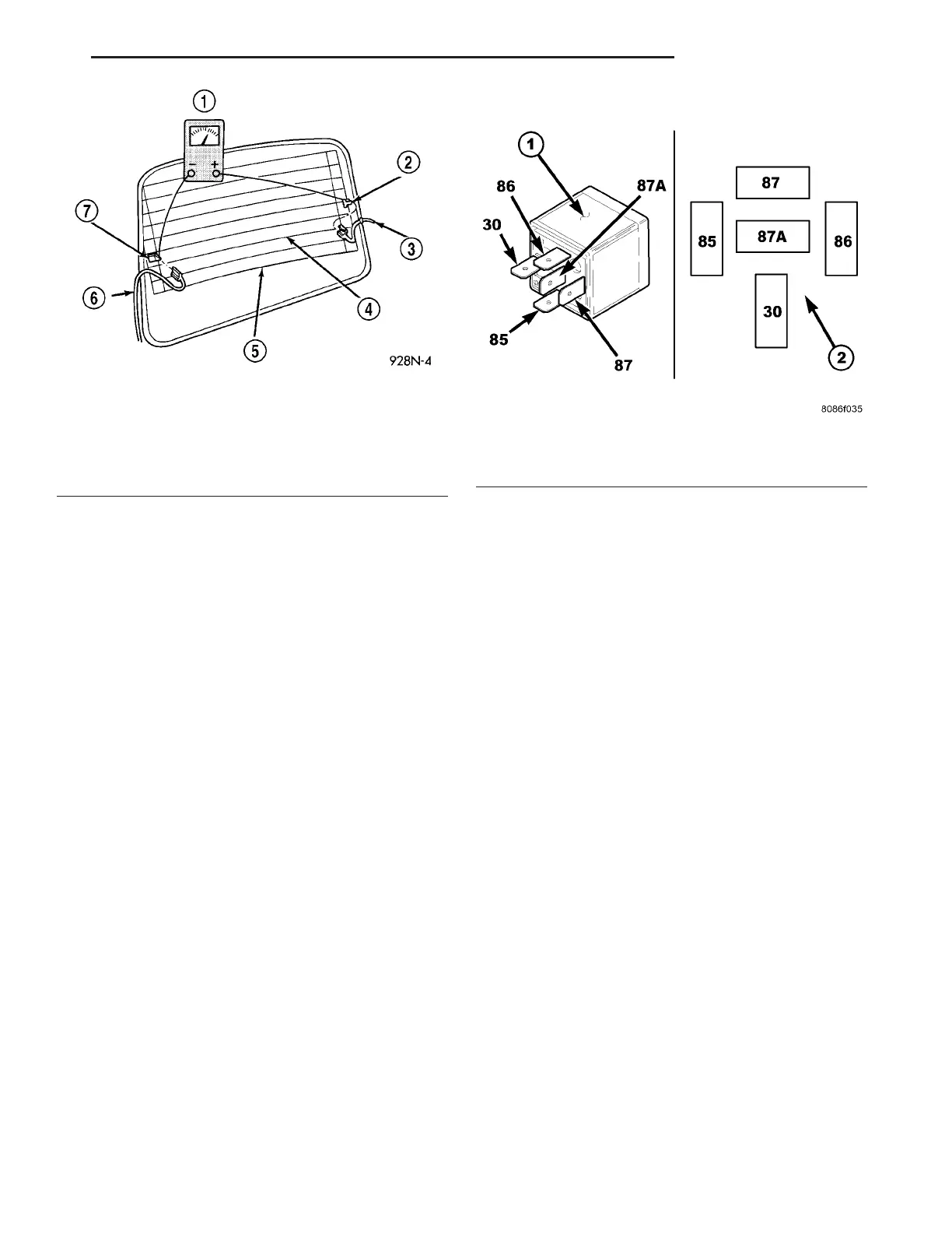
Fig. 2 Grid Line Test
1 - VOLTMETER
2 - VOLTAGE FEED (A)
3 - FEED WIRE
4 - MID-POINT (C)
5 - HEATED WINDOW GRID
6 - GROUND WIRE
7 - GROUND (B)
Fig. 3 Rear Window Defogger (EBL) Relays
1 - REAR WINDOW DEFOGGER (EBL) RELAY (2)
2 - TERMINAL PATTERN
VA HEA TED GLASS 8G - 3