• Th e coil gr ound t erminal (86) is har dwired to
ground point G202.
• Th e coil ba tter y ter mina l (85) receives a battery
curren t input from t he r ear window defogger module
when th e rea r window defogger switch is energized.
• Th e nor mally open termina l (87) provides a bat-
tery current out pu t to the r ear window defogger grid
lin es th rough the r elay ou tput circuit on ly when th e
rear window defogger r elay coil is en ergized.
• Th e normally closed ter minal (87A) is not con-
nected to any circuit in this application, but pr ovides
a ba tter y current out put only wh en the rea r window
defogger rela y coil is de-energized.
The left and right E BL relays cann ot be repa ired
and, if fau lty or damaged, they must be replaced.
Refer to the appropriate wiring in forma tion for dia g-
nosis and testing of the EBL relays and for complete
rear window defogger system wirin g diagram s.
REMOVAL
(1) Disconn ect and isolate the negat ive ba tter y
cable.
(2) Remove the cover from the fuse/relay block
(Fig. 4).
NOTE: Refer to the fuse and relay map located on
the inner surface of the fuse/relay block cover for
the left and right rear window defogger (EBL) relay
locations.
(3) Remove the EBL relays from t he fuse/relay
block as requ ired.
INSTALLATION
NOTE: Refer to the fuse and relay map located on
the inner surface of the fuse/relay block cover for
the left and right rear window defogger (EBL) relay
locations.
(1) Position th e rear window defogger (EBL) relays
as requir ed into their pr oper recepta cles in th e fuse/
rela y block.
(2) Align t he EBL r elay t erminals with the t ermi-
nal cavities in the fuse/relay block receptacles.
(3) Push down firmly on the EBL relays until the
term inals a re fully seated in th e ter min al cavities in
the fu se/relay block receptacles.
(4) In st all the cover onto the fuse/relay block.
(5) Reconnect t he negat ive batt ery cable.
REAR WI N DOW DEFOGGER
SWI T CH
DESCRIPTION
The rear win dow defogger switch is mou nted in the
instr umen t pan el to th e right of the steerin g wheel
(Fig. 5). The rea r window defogger switch conta ins a
yellow indicator la mp th at illuminat es when th e r ear
window defogger (EBL) system is a ctivated.
The rea r window defogger switch an d th e defogger
switch indica tor can not be repaired and, if fau lty or
da maged, the r ear window defogger switch must be
repla ced.
OPERATION
A yellow indicator lamp will illum inate when the
rear window defogger swit ch is activated. The switch
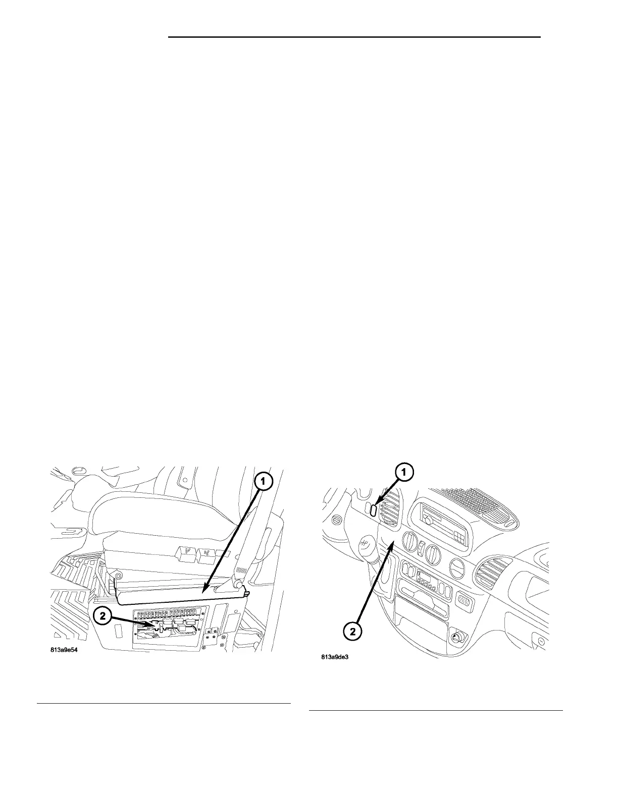
Fig. 4 Rear Window Defogger (EBL) Relays
1 - DRIVERS SEAT
2 - FUSE/RELAY BLOCK
Fig. 5 Rear Window Defogger Switch
1 - REAR WINDOW DEFOGGER SWITCH
2 - INSTRUMENT PANEL
8G - 4 H EAT ED GL AS S VA