Accessing Internal Components
DSX™ System Service Manual 16-5
To Remove the Right Side Panel:
3 Remove the M6X25mm screw and M6 flat washer from the upright extrusion
spring nut.
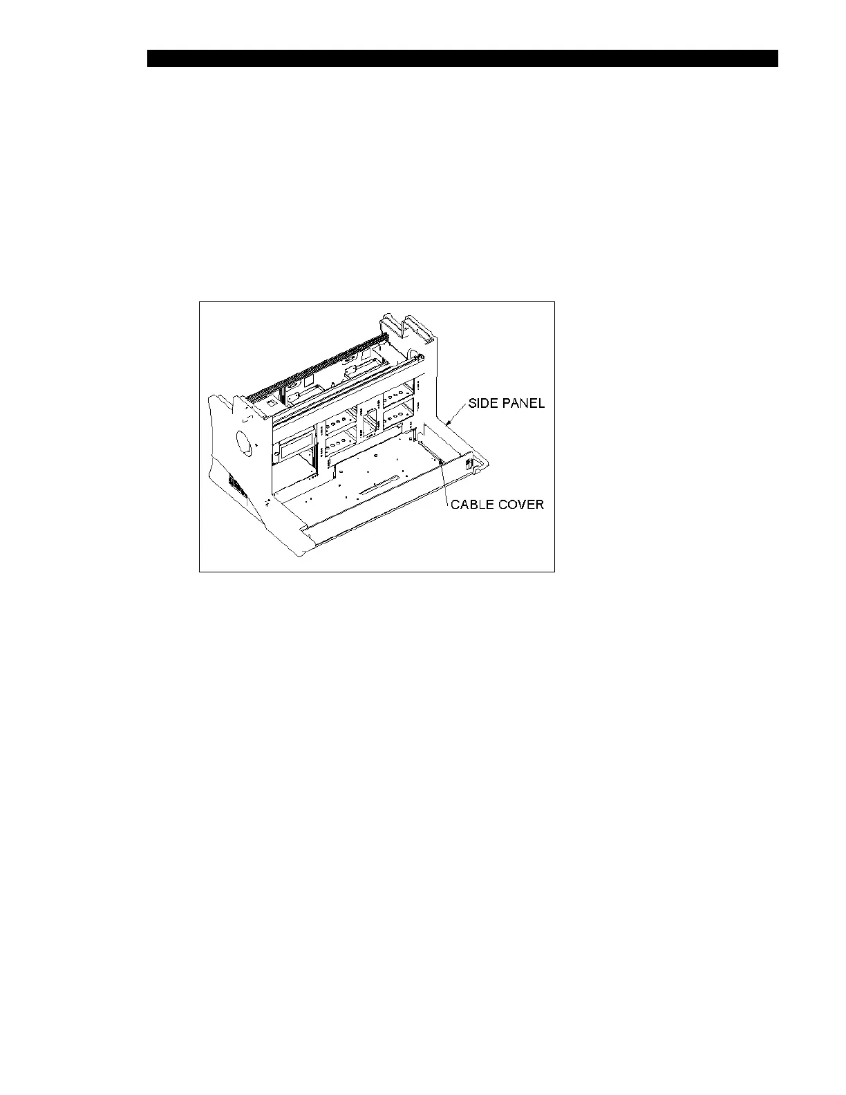
1 Remove the right cable cover (Part No. 204023400) by removing the four
M4 x 8 BHCS Screws (Figure 16-5).
2 Remove the three M6 X 12mm BHCS screws that attach the right side panel from
the top of the baseplate (two in front, one in rear) as shown in Figure 16-4.
Figure 16-5 Right Cable Cover
To Replace the Right Side Panel:
3 Secure with three M6 X 12mm BHCS screws into the top of the base plate (two in
the front, one in the rear).
1 Install the right-hand side panel enclosure (Part No. 204012600) and make sure
that the spring nut in the 80 X 40 upright extrusion is aligned with hole in the side
panel. If necessary, move the spring nut up (down) until it is correctly located.
2 Secure with one M6 X 25mm SHCS and M6 flat washer into the upright extrusion
spring nut.