168
Balance and Differential Modes
When adjusting a video signal in balanced or in differential mode, the associated waveforms
will appear differently as shown below. A 100% color bar signal is used in the following
example.
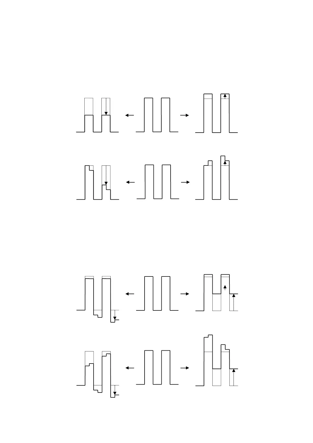
(1)The figures below illustrate the change of the signal waveform when the WHITE level is
adjusted along the R axis. This also applies to the G or B axis.
BALANCE mode
DIFFERENTIAL mode
Notice that on vectorscope displays the signal level transition in the above example is
different between balanced and differential modes when observing the R, G or B axis positive
territories.
(2) The figures below illustrate the change in signal waveform when the BLACK level is
adjusted along the R axis in balanced or differential mode. These changes will also be
applied to the G or B axis.
BALANCE mode
DIFFERENTIAL mode
When set to a negative value:
When set to a positive value:
When set to a negative value:
When set to a positive value:
When set to a negative value:
When set to a positive value:
When set to a negative value:
When set to a positive value:


 To Next Page