GE HEALTHCAREDRAFT LOGIQ™ S7 EXPERT/PRO
DIRECTION 5460683, REVISION 3 DRAFT (JUNE 25, 2014) SERVICE MANUAL
Chapter 8 - Replacement Procedures 8-67
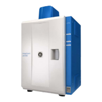
3.) Pullout AN Key Top Assy from Keyboard Fame. Refer to below Figure 8-62.
Figure 8-62 Pullout the AN key Top Assy
4.) Replace old AN Key Top ASSY with the New AN Key Top ASSY.
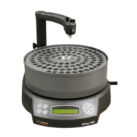
5.) Push the 8 points to make AN key Top Assy strongly attach to Key frame refer to below Figure 8-63.
Figure 8-63 Push the AN key Top Assy
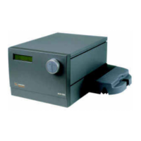
6.) Remove ‘1’ Key, ‘Left Shift’ Key, ‘F5’ Key, ‘6’ Key, ‘7’ Key, ‘H’ Key, ‘J’ Key, ‘N’ Key, ‘Back space’
Key, ‘Right Shift’ Key and ‘Pg Up’ Key by using fingertips. Refer to procedure ‘2).’
7.) Tighten the 6 screws using the plus(+) screwdriver. Refer to Refer to below Figure 8-64.
Figure 8-64 Tighten the 6 screws
8.) Insert ‘1’ Key, ‘Left Shift’ Key, ‘F5’ Key, ‘6’ Key, ‘7’ Key, ‘H’ Key, ‘J’ Key, ‘N’ Key, ‘Back space’ Key,
‘Right Shift’ Key and ‘Pg Up’ Key.
 Loading...