GE HEALTHCAREDRAFT LOGIQ™ S7 EXPERT/PRO
DIRECTION 5460683, REVISION 3 DRAFT (JUNE 25, 2014) SERVICE MANUAL
Chapter 10 - Care & Maintenance 10-25
10-8-4 Grounding Continuity
Measure the resistance from the third pin of the attachment plug to the exposed protectively - earthed
metal parts of the case. The ground wire resistance should be less than 0.2 ohms.
Reference the procedure in the IEC60601-1.
10-8-4-1 Meter Procedure
Follow these steps to test the Ground wire resistance.
1.) Turn the system unit OFF.
2.) Plug the unit into the meter, and the meter into the tested AC wall outlet.
3.) Plug the black chassis cable into the meter’s “CHASSIS” connector and attach the black chassis
cable clamp to an exposed protectively earthed metal part of the system, such as Potential
equilibrium connector.
4.) Set the meter’s “FUNCTION” switch to the RESISTANCE position.
5.) Set the meter’s “POLARITY” switch to the OFF (center) position.
6.) Measure and record the Ground wire resistance. This should be less than 0.2 Ohms.
!! CAUTION:
Electric Shock Hazard!
The patient or operator MUST NOT come into contact with the equipment during this test
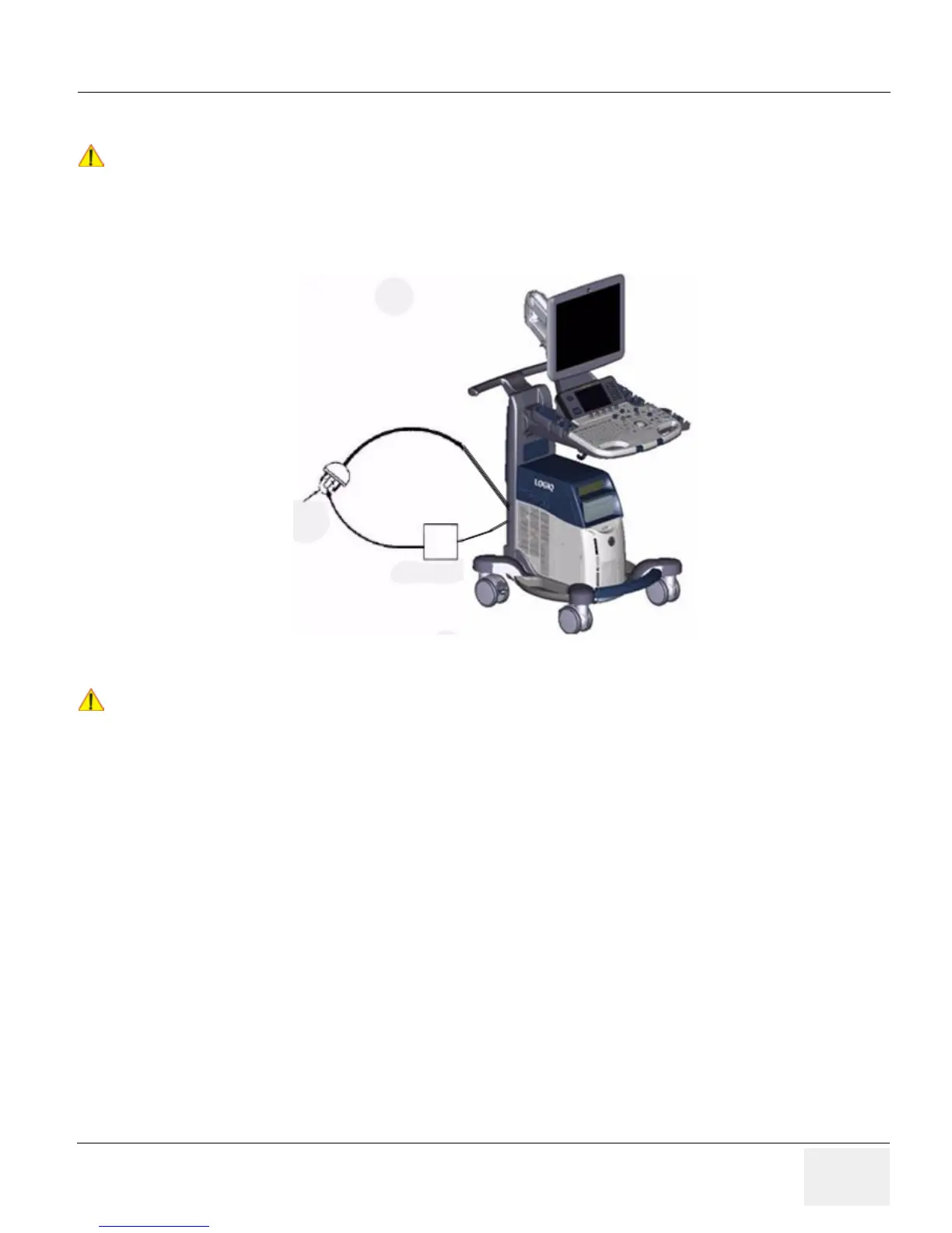
Figure 10-16 Ground Continuity Test
!! CAUTION:
Lacquer is an isolation barrier! Resistor may be high-impedance!
Measure only on blank parts, stated in Figure 10-16 above.
 Loading...