iPECS eMG80/100& eMG800 & UCP & vUCP
Administration and Programming Manual Issue 2.5
174
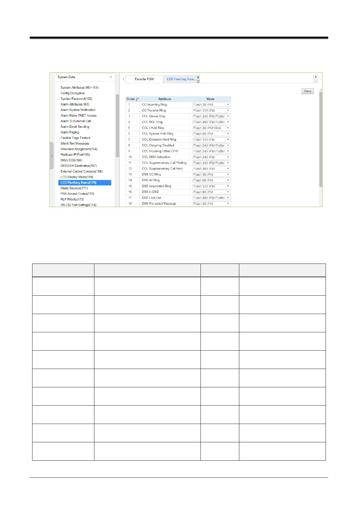
4.4.5.18 LED Flashing Rate - PGM 170
Selecting LED Flashing Rate will display the data entry page. Click the [Save] button after changing Value.
Figure 4.4.5.18-1 LED Flashing Rate
The LED flash rate for various functions and states can be assigned any one of the system‘s 15 signals. The
various functions and states are shown in the following table. The 15 flash signals available in the system are
shown in the table ‘LED flash rate.’
Table 4.4.5.18-1 LED INDICATION
CO button Incoming ring flashing rate.
It is CO button transfers ring flashing
rate.
It is CO button queue callback ring
flashing rate.
It is CO button recall ring flashing rate.
CO button I hold flashing rate.
CO button system holds flashing rate.
CO button exclusives hold flashing
rate.
It is CO button outgoing disabled
flashing rate.
CO button incoming off-net call
forward flashing rate.
It is CO button DISA indication flashing
rate.