3 - 4
Chapter 3 Removal and Replacement Procedures (RRPs)
RRP1. COVERS
RRP1.1 COVER REAR (PL 1.1)
Removal
1) Remove the 500 COVER REAR (PL 7.1) (RRP7.9)
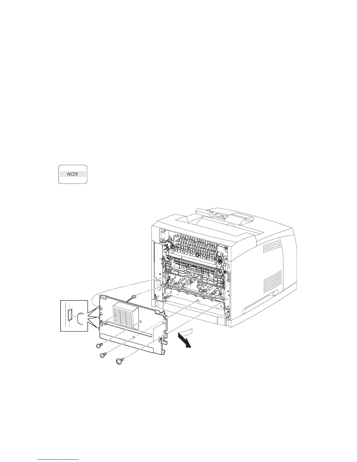
2) Remove the 5 screws (silver with flange, 8mm x 2, gold tapping, 8mm x 3) securing the COVER
REAR to the printer (Figure 1).
3) Open the COVER REAR in the direction of the arrow. Release the 3 hooks securing the COVER
REAR to the printer, and remove it from the printer.
4) Disconnect the connector (P/J244).
Replacement
1) Connect the connector (P/J244).
2) Insert the 3 hooks on the left side of the COVER REAR into the 3 holes of the printer (Figure 1).
3) Secure the COVER REAR to the printer using the 5 screws (silver with flange, 8mm x 2, gold tap-
ping, 8mm x 3).
There are 2 kinds of screws, make sure they are installed correctly.
When tightening the screws be careful not to pinch the harness between the board
and frame.
4) Install the 500 COVER REAR (PL 7.1.21). (RRP7.9)
Figure 1. Cover Rear
J23143AA

 Loading...


