3 - 50
Chapter 3 Removal and Replacement Procedures (RRPs)
RRP3.8 GUIDE INDICATOR 3 (PL 3.1.36)
Removal
1) Remove the COVER CST (PL 12.3) from the 550 PAPER CASSETTE.
2) Remove the HANDLE EXTENSION 550 (PL 3.1) (RRP3.7).
When removing the HANDLE EXTENSION 550, the LOW INDICATOR (PL 3.1) and LOW
IND FRONT (PL 3.1) will be detached. Be careful not to lose them.
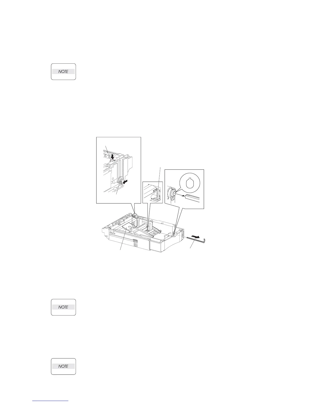
3) While pressing down the lock of the STOPPER GEAR (PL 12.3), release the lock of the LEVER
BTM LOCK (PL 3.1) to lift up the PLATE ASSEMBLY BTM (PL 3.1).
4) Remove the link lever of the GUIDE INDICATOR 1 (PL 3.1) from the hole of the PLATE ASSEM-
BLY BTM (Figure 1).
5) While pressing the link lever down to the bottom side of the 550 PAPER CASSETTE, slowly but
firmly pull the GUIDE INDICATOR 3 out from the front side of the HOUSING EXTENSION 550 (PL
3.1).
Figure 1. Guide Indicator
Replacement
1) While pressing the link lever down to the bottom side of the 550 PAPER CASSETTE, insert the
GUIDE INDICATOR 3 to the HOUSING EXTENSION 550 (PL 3.1) from the front side.
Be sure to align the groove of the GUIDE INDICATOR 1 and the projection of the GUIDE
INDICATOR 3.
2) Insert the link lever of the GUIDE INDICATOR 1 (PL 3.1) to the hole of the PLATE ASSEMBLY
BTM.
3) Install the LOW INDICATOR (PL 3.1) and LOW IND FRONT (PL 3.1) (RRP3.10).
4) Install the HANDLE EXTENSION 550 (PL 3.1) (RRP3.7)
5) Install the COVER CST (PL 12.3) to the 550 PAPER CASSETTE.
After assembling, make sure that the LOW IND FRONT moves up-and-down in conjunc-
tion with the up-and-down movement of the PLATE ASSEMBLY BTM
JG3027AA
GUIDE INDICATOR 3
(PL4.1.36)
GUIDE INDICATOR 1
LEVER BTM LOCK
(PL4.1.27)
STOPPER GEAR
(PL4.1.29)
PLATE ASSY BTM
(PL4.1.10)

 Loading...


