3 - 150
Chapter 3 Removal and Replacement Procedures (RRPs)
RRP9.3 LVPS (PL 9.1.5)
Removal
1) Remove the COVER REAR 500 (PL 7.1) (RRP7.9).
2) Remove the COVER REAR (PL 1.1) (RRP1.1).
3) Remove the COVER LEFT (PL 1.1) (RRP1.3).
4) Remove the COVER RIGHT (PL 1.1) (RRP1.2).
5) Remove the COVER EXIT 500 (PL 1.1) (RRP7.1).
6) Remove the 500 EXIT ASSEMBLY (PL 7.1) (RRP7.2).
7) Remove the COVER TOP (PL 1.1) (RRP1.4).
8) Remove the COVER FRONT (PL 1.1) (RRP1.5).
9) Remove the SHIELD PLATE LVPS (PL 9.1) (RRP8.1).
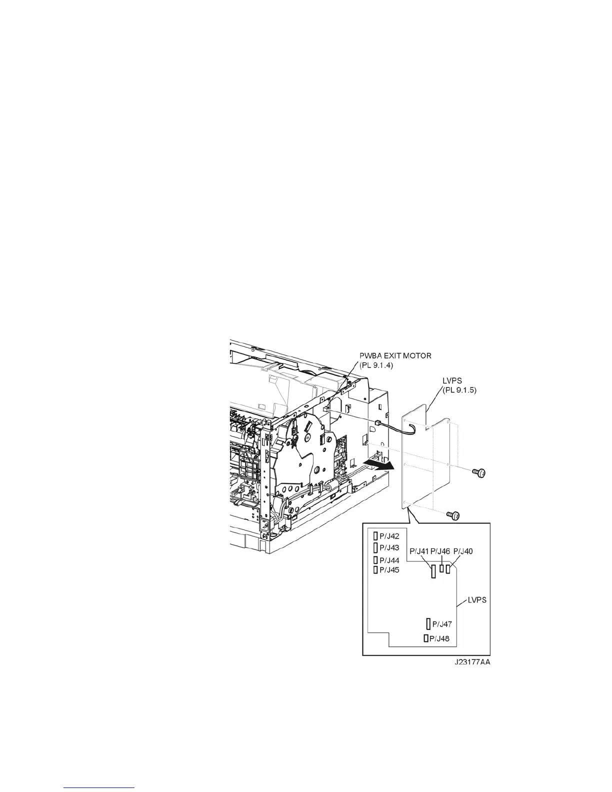
10) Disconnect the harness connector from the connector (P/J101) on the PWBA EXIT MOTOR (PL
9.1.4) (Figure 1).
11) Disconnect the harness connectors from the connectors (P/J40, P/J41, P/J42, P/J43, P/J44, P/
J45, P/J46, P/J47 and P/J48) on the LVPS (Figure 1).
12) Remove the 5 screws (silver, 6mm) securing the LVPS to the frame (Figure 1).
13) Remove the LVPS.
Figure 1. Low Voltage Power Supply (LVPS)