3 - 82
Chapter 3 Removal and Replacement Procedures (RRPs)
RRP5.5 CLUTCH ASSEMBLY PH (PL 5.1.20)
Removal
1) Remove the COVER REAR 500 (PL 7.1) (RRP7.9).
2) Remove the FUSER ASSEMBLY (PL 6.1) (RRP6.8).
3) Remove the COVER REAR (PL 1.1) (RRP1.1).
4) Remove the CHUTE TRANSFER (PL 6.1) together with the BTR ASSEMBLY (RRP6.9).
5) Remove the 150 FEEDER ASSEMBLY (PL 4.1) (RRP4.1).
6) Remove the 550 FEEDER ASSEMBLY (PL 5.1) (RRP5.1).
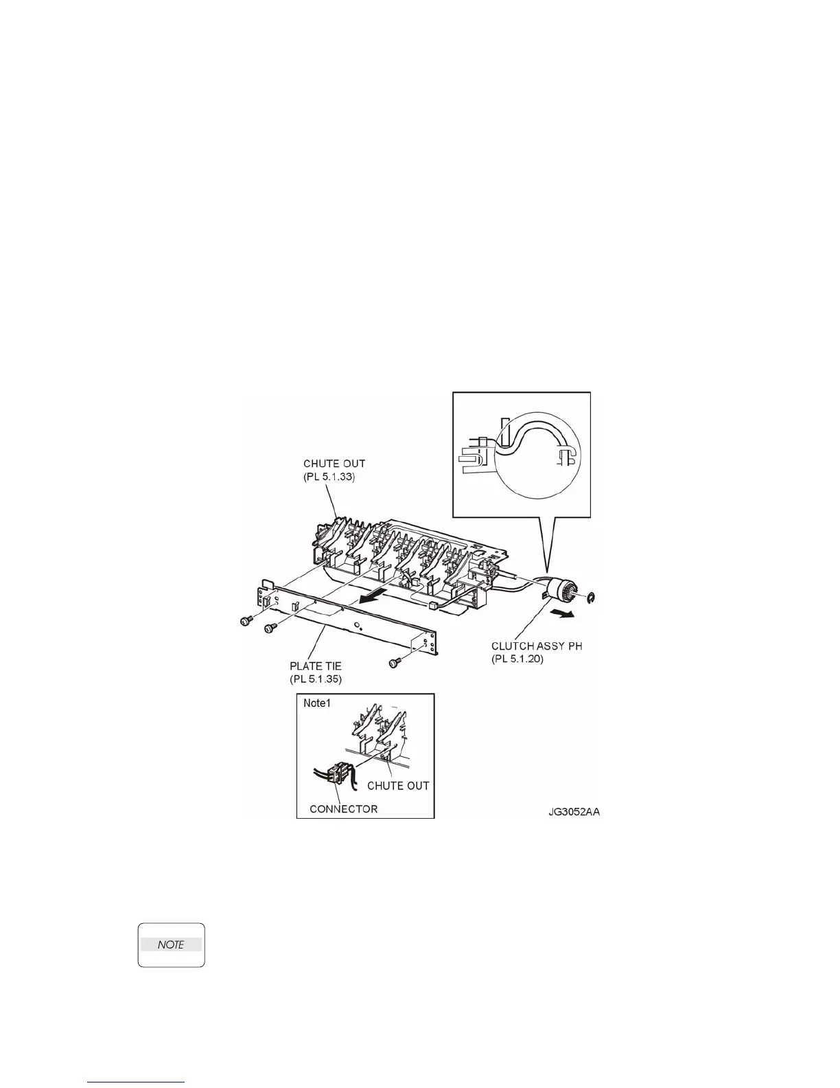
7) Remove the 6 screws (gold tapping, 8mm) securing the PLATE TIE (PL 5.1) to the CHUTE OUT
(PL 5.1), and remove the PLATE TIE from the CHUTE OUT (Figure 1).
8) Disconnect the connector (P/J247) of the CLUTCH ASSEMBLY PH from the HARNESS ASSEM-
BLY TRAY 2 (PL 5.1) (Figure 1).
9) Remove the E-ring securing the CLUTCH ASSEMBLY PH, and remove the CLUTCH ASSEMBLY
PH from the SHAFT FEED (PL 5.1) (Figure 1).
Figure 1. PH Clutch Assembly
Replacement
1) Install the CLUTCH ASSEMBLY PH to the SHAFT FEED (PL 5.1), and secure it using the E-ring.
When installing, make sure that the notch of the CLUTCH ASSEMBLY PH is combined
with the boss of the CHUTE OUT.
2) Connect P/J247 of the CLUTCH ASSEMBLY PH to the HARNESS ASSEMBLY TRAY 2 (PL 5.1).
After connecting, put the connector into the space between the ribs of the CHUTE OUT (Figure 1).

 Loading...


