3 - 112
Chapter 3 Removal and Replacement Procedures (RRPs)
RRP6.11 PWBA ASSEMBLY ANT (PL 6.1.23)
Removal
1) Remove the COVER REAR 500 (PL 7.1) (RRP7.9).
2) Remove the COVER REAR (PL 1.1) (RRP1.1).
3) Remove the FUSER ASSEMBLY (PL 6.1) (RRP6.8).
4) Remove the COVER LEFT (PL 1.1) (RRP1.3).
5) Remove the COVER RIGHT (PL 1.1) (RRP1.2).
6) Remove the COVER EXIT 500 (PL 1.1) (RRP7.1).
7) Remove the 500 EXIT ASSEMBLY (PL 7.1 (RRP7.2).
8) Remove the COVER TOP (PL 1.1) (RRP1.4).
9) Remove the COVER FRONT (PL 1.1) (RRP1.5).
10) Remove the BTR ASSEMBLY (PL 6.1) (RRP6.9).
11) Remove the DUCT FRONT (PL 6.1) (RRP6.2).
12) Remove the GUIDE ASSEMBLY CRU R (PL 6.1) (RRP6.12)
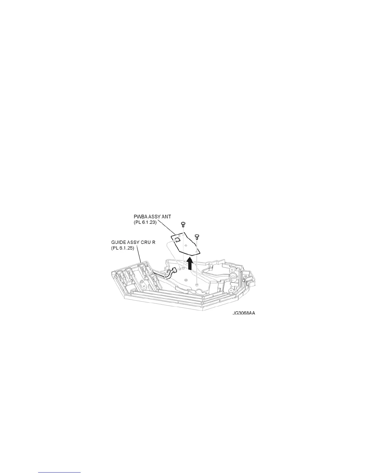
13) Remove the 2 screws (gold tapping, 6mm) securing the PWBA ASSEMBLY ANT to the GUIDE
ASSEMBLY CRU R (Figure 1).
14) Remove the PWBA ASSEMBLY ANT (Figure 1).
15) Disconnect the harness connector from the connector (P/J150) on the PWBA ASSEMBLY ANT
(Figure 1).
Figure 1. ANT PWBA Assembly
Replacement
1) Connect the harness connector to the connector (P/J150) on the PWBA ASSEMBLY ANT (Figure
1).
2) Install the PWBA ASSEMBLY ANT to the GUIDE ASSEMBLY CRU R (PL 6.1) using the 2 screws
(gold tapping, 6mm) (Figure 1).
3) Install the GUIDE ASSEMBLY CRU R (PL 6.1) (RRP6.12).
4) Install the DUCT FRONT (PL 6.1) (RRP6.2).
5) Install the COVER FRONT (PL 1.1) (RRP1.5).
6) Install the COVER TOP (PL 1.1) (RRP1.4).
7) Install the 500 EXIT ASSEMBLY (PL 7.1) (RRP7.2).
8) Install the COVER EXIT 500 (PL 1.1) (RRP7.1).
9) Install the COVER RIGHT (PL 1.1) (RRP1.2).
10) Install the COVER LEFT (PL 1.1) (RRP1.3).

 Loading...


