3 - 23
Chapter 3 Removal and Replacement Procedures (RRPs)
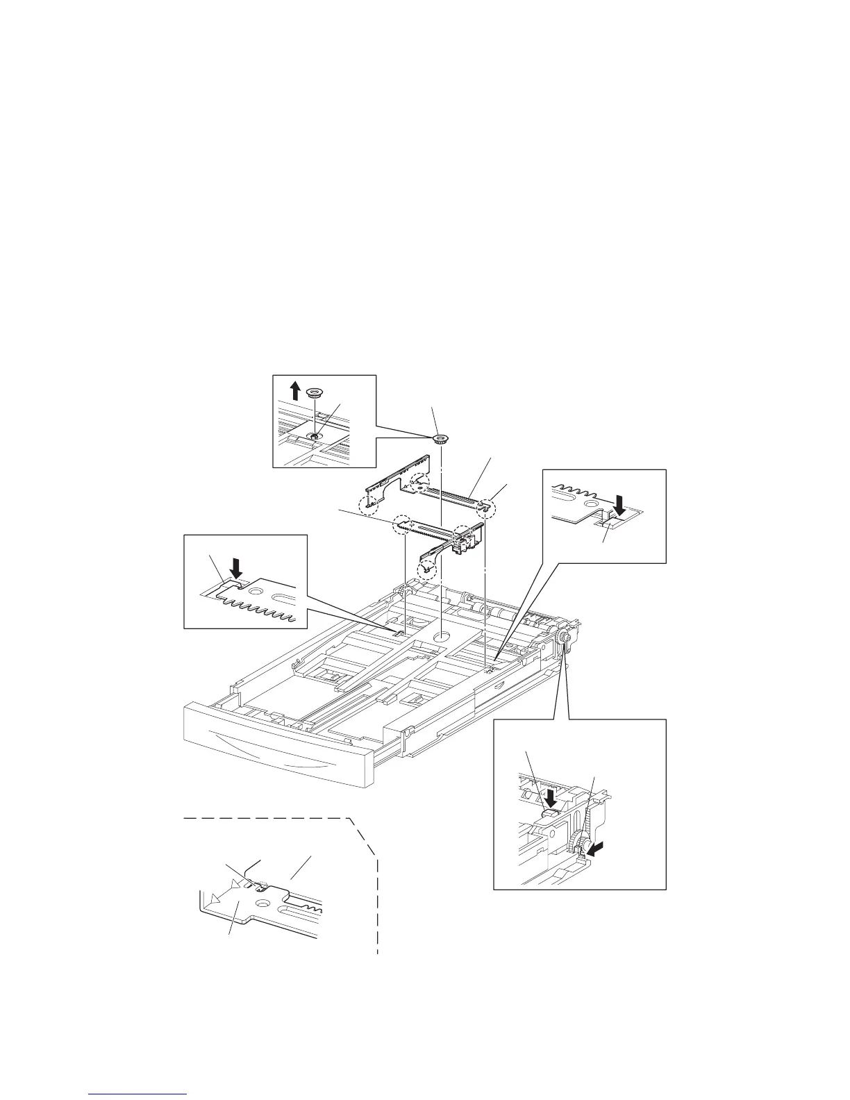
RRP2.5 PLATE ASSEMBLY BTM (PL 2.1)
Removal
1) Remove the COVER CST (PL 2.1) from the 150 PAPER CASSETTE (Figure 1).
2) Release the lock of the LOCK EXTENSION, and pull out the cassette extension as far as it will go
(Figure 1).
3) Release the hooks securing the GEAR PINION (PL 2.1) to the HOUSING TOP 150 (PL 2.1), and
remove the GEAR PINION.
4) While pressing down the lock of the STOPPER GEAR (PL 2.1), release the lock of the LEVER
BTM LOCK (PL 2.1) to lift up the PLATE ASSEMBLY BTM (PL 2.1).
5) Slide the GUIDE ASSEMBLY SD L150 (PL 2.1) inward, and remove it from the HOUSING TOP
150 by pressing down the hook of the HOUSING TOP 150.
6) Slide the GUIDE ASSEMBLY SD R150 (PL 2.1) inward, and remove it from the HOUSING TOP
150 by pressing down the hook of the HOUSING TOP 150.
Figure 1. Plate Assembly BTM
HOOKS
GUIDE ASSY SD L150
(PL2.1.11)
GUIDE ASSY SD R150
(PL2.1.13)
GEAR PINION
(PL2.1.12)
HOOK
HOOK
JG3012AAGUIDE ASSY SD L150
WHEN ASSEMBLING
CLAW
HOUSING TOP150
LEVER BTM LOCK
(PL2.1.26)
STOPPER GEAR
(PL2.1.28)
CLAWS