3 - 46
Chapter 3 Removal and Replacement Procedures (RRPs)
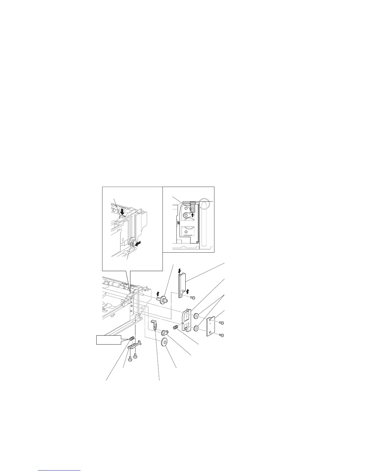
RRP3.6 GEAR LEVER LOCK (PL 3.1.26), LEVER BTM LOCK (PL 3.1)
Removal
1) Remove the COVER CST (PL 12.3) from the 550 PAPER CASSETTE.
2) Release the lock of the LOCK EXTENSION, and pull out the cassette extension as far as it will go.
3) While pressing down the lock of the STOPPER GEAR (PL 12.3), release the lock of LEVER BTM
LOCK (PL 3.1) to lift up the PLATE ASSEMBLY BTM (PL 3.1).
4) Remove the screw (gold tapping, 8mm) securing the PLATE GEAR LOCK 550 (PL 3.1) at the
GEAR PB R (PL 3.1) side.
5) Release the hook of the PLATE GEAR LOCK 550, and remove it from the HOUSING BASE 550
(PL 3.1).
6) Release the hook of the GEAR PB R, and remove the GEAR PB R from the SHAFT PB (PL 3.1).
7) Remove the 2 screws (gold tapping, 6mm) securing the COVER BTM UP 550 (PL 3.1), and
remove it from the HOUSING BASE 550.
8) Remove 2 GEAR LOCK PINIONs (PL 3.1) from the HOUSING BASE 550 (Figure 1).
9) Remove the RACK BTM LOCK 550 (PL 3.1) together with the SPRING BTM LOCK (PL 3.1) from
the HOUSING BASE 550 (Figure 1).
Figure 1. Gear Lever & Lever BTM Lock
10) Remove the GEAR BTM LOCK (PL 3.1) from the HOUSING BASE 550.
11) Remove the GEAR LEVER LOCK from the HOUSING BASE 550.
12) Remove the 2 screws (gold tapping, 6mm) securing the STOPPER GEAR (PL 12.3), and remove
the STOPPER GEAR and SPRING STOPPER GEAR (PL 3.1) from the HOUSING BASE 550.
SPRING BTM LOCK
(PL4.1.24)
LEVER BTM LOCK
(PL4.1.27)
STOPPER GEAR
(PL4.1.29)
GEAR LEVEL LOCK
(PL4.1.26)
(PL4.1.23)
GEAR BTM LOCK
(PL4.1.25)
RACK BTM LOCK 550
(PL4.1.21)
COVER BTM UP 550
(PL4.1.22)
SPRING STOPPER GEAR
(PL4.1.28)
PLATE GEAR LOCK 550
(PL4.1.19)
GEAR PB R
(PL4.1.20)
NOTE1)
STOPPER
LEVER BTM LOCK
(PL4.1.27)
STOPPER GEAR
(PL4.1.29)
JG3137AA
SEE NOTE2
GEAR BTM LOCK PINION
(PL 3.1.27)
(PL 3.1.29)
(PL 3.1.20)
(PL 3.1.19)
(PL 3.1.21)
(PL 3.1.23)
(PL 3.1.22)
(PL 3.1.24)
(PL 3.1.26)
(PL 3.1.25)
(PL 3.1.27)
(PL 3.1.29)
(PL 3.1.28)

 Loading...


