3 - 139
Chapter 3 Removal and Replacement Procedures (RRPs)
RRP8.1 MOTOR COVER (PL 8.1)
Removal
1) Remove the COVER REAR 500 (PL 7.1) (RRP7.9).
2) Remove the COVER REAR (PL 1.1) (RRP1.1).
3) Remove the FUSER ASSEMBLY (PL 6.1) (RRP6.8).
4) Remove the COVER LEFT (PL 1.1) (RRP1.3).
5) Remove the COVER RIGHT (PL 1.1PL 1.1) (RRP1.2).
6) Remove the COVER EXIT 500 (PL 1.1) (RRP7.1).
7) Remove the 500 EXIT ASSEMBLY (PL 7.1) (RRP7.2).
8) Remove the COVER TOP (PL 1.1) (RRP1.4).
9) Remove the COVER FRONT (PL 1.1) (RRP1.5).
10) Remove the BTR ASSEMBLY (PL 6.1) (RRP6.9).
11) Remove the GUIDE TRAY LEFT (PL 5.1) (RRP5.8).
12) Remove the DUCT FRONT (PL 6.1) (RRP6.2).
13) Remove the ROS ASSEMBLY (PL 6.1) (RRP6.1).
Be careful not to drop or strike the ROS Assembly with any tools or other objects.
14) Remove the SHIELD PLATE ROS (PL 6.1) (RRP6.3).
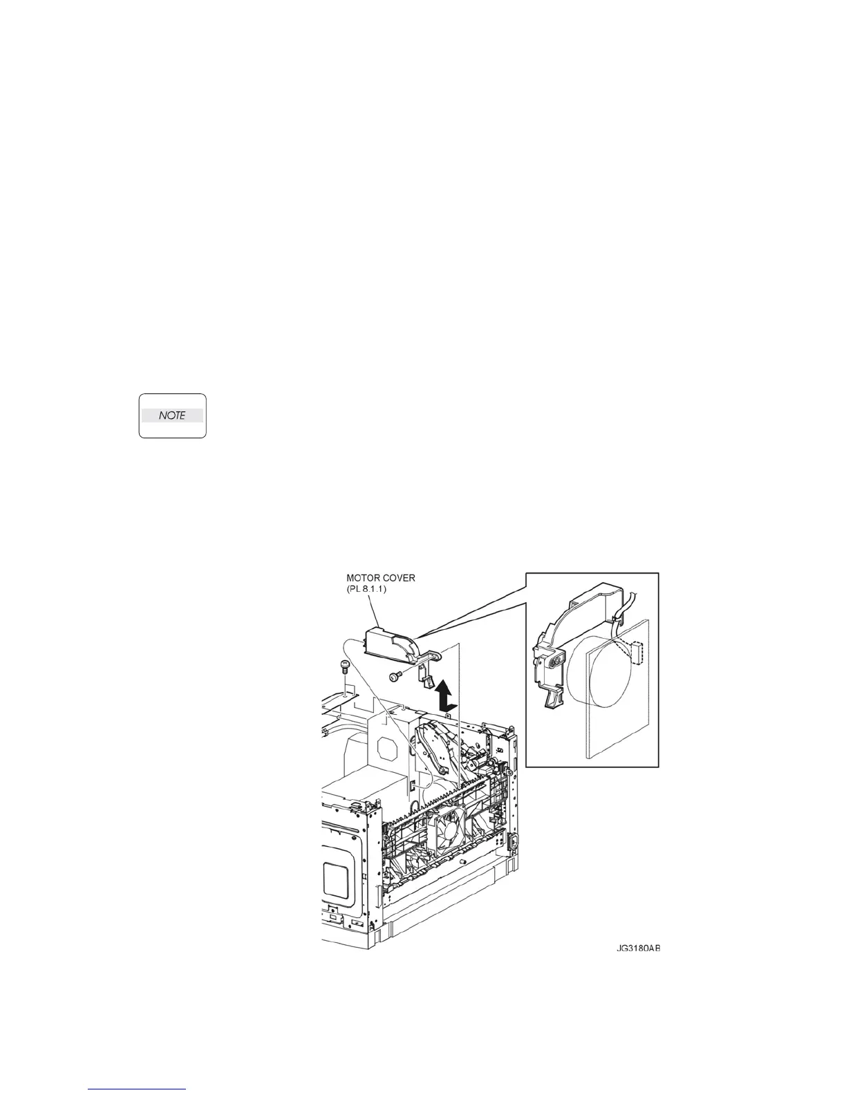
15) While lifting up the 150 FEEDER ASSEMBLY, remove the screw (silver, 6mm) securing the
MOTOR COVER to the frame (Figure 1).
16) Remove the harness connector of MAIN MOTOR (Figure 1).
17) Remove the MOTOR COVER (Figure 1).
Figure 1. Motor Cover

 Loading...


