3 - 236
Chapter 3 Removal and Replacement Procedures (RRPs)
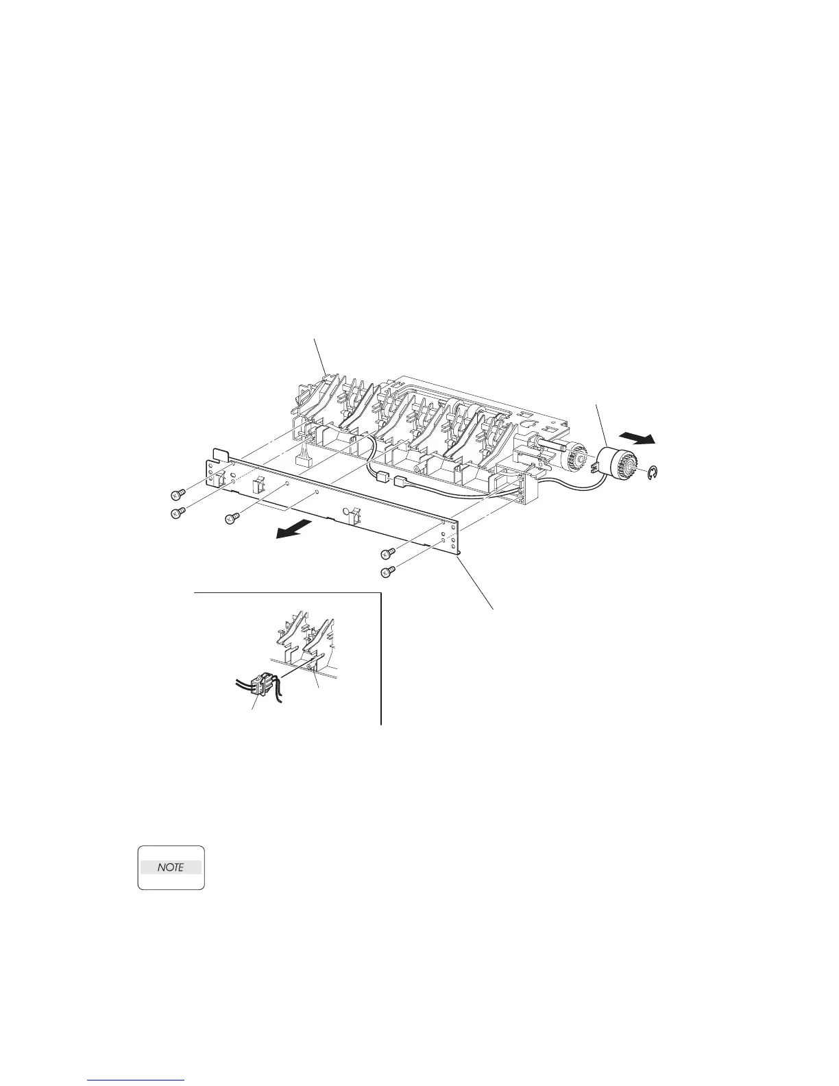
RRP12.15CLUTCH PR-REGI (PL12.2)
Removal
1) Remove the 550 FEEDER OPTION (PL 12.2). (RRP12.1)
2) Remove the 6 screws (gold taping, 8mm) securing the PLATE TIE (PL 12.2.29).
3) Remove the PLATE TIE from the CHUTE OUT (PL 12.2.25).
4) Disconnect the connector (P/J854) of the CLUTCH PR-REGI from the HARNESS ASSY
CLSNR1 (PL 12.2.31).
5) Remove the E-ring securing the CLUTCH PR-REGI, and remove the CLUTCH PR-REGI from
the ROLL ASSY TURN (PL 12.2.14).
Replacement
1) Install the CLUTCH PR-REGI to the ROLL ASSY TURN (PL 12.2.14), and secure it with the E-
ring.
When installing, make sure that the notch of the CLUTCH PR-REGI is combined with the
boss of the CHUTE OUT.
2) Connect the connector (P/J854) of the CLUTCH PR-REGI to the HARNESS ASSY CLSNR1
(PL 12.2.31). After connecting the connector, put the connector into the space between two
ribs of the CHUTE OUT (PL 12.2.25).
3) Install the PLATE TIE (PL 12.2.29) to the CHUTE OUT using the 6 screws (gold tapping,
8mm).
4) Install the 550 FEEDER OPTION (PL 12.2). (RRP12.1)
JG3516AA
CHUTE OUT
(PL20.2.25)
CLUTCH PR-REGI
(PL20.2.22)
PLATE TIE
(PL20.2.29)
CONNECTOR
CHUTE OUT
WHEN ASSEMBLING

 Loading...


