3 - 154
Chapter 3 Removal and Replacement Procedures (RRPs)
RRP9.5 INTERLOCK S/W REAR (PL 9.1.7)
Removal
1) Remove the COVER REAR 500 (PL 7.1) (RRP7.9).
2) Remove the COVER REAR (PL 1.1) (RRP1.1).
3) Remove the COVER LEFT (PL 1.1) (RRP1.3).
4) Remove the COVER RIGHT (PL 1.1) (RRP1.2).
5) Remove the COVER EXIT 500 (PL 1.1) (RRP7.1).
6) Remove the 500 EXIT ASSEMBLY (PL 7.1) (RRP7.2).
7) Remove the COVER TOP (PL 1.1) (RRP1.4).
8) Remove the COVER FRONT (PL 1.1) (RRP1.5).
9) Remove the SHIELD PLATE LVPS (PL 9.1) (RRP8.1).
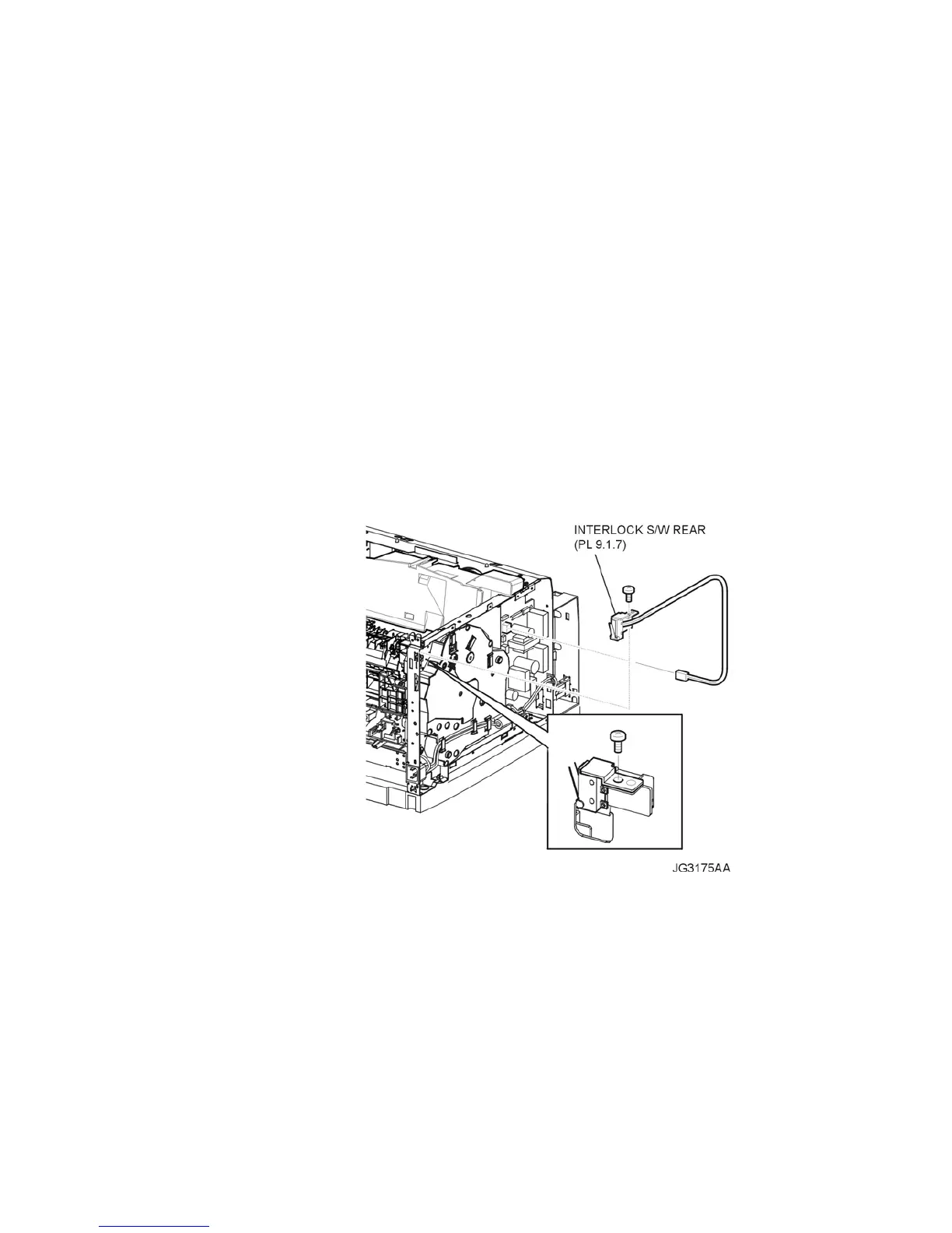
10) Disconnect the connector (P/J44) of the INTERLOCK S/W REAR from the LVPS (PL 9.1.5) (Fig-
ure 1).
11) Release the clamps of the HARNESS ASSEMBLY INTERLOCK 2 of the INTERLOCK S/W REAR
from the clamps on the GEAR ASSEMBLY HOUSING (PL 8.1.3) (Figure 1).
12) Remove the screw (silver, 6mm) securing the INTERLOCK S/W REAR to the frame (Figure 1).
13) Remove the INTERLOCK S/W REAR.
Figure 1. Rear Interlock Switch
Replacement
1) Install the INTERLOCK S/W REAR to the frame using the screw (silver, 6mm) (Figure 1).
2) Secure the HARNESS ASSEMBLY INTERLOCK 2 of the INTERLOCK S/W REAR to the clamps
on the GEAR ASSEMBLY HOUSING (PL 8.1.3) (Figure 1).
3) Connect the connector (P/J44) of the INTERLOCK S/W REAR to the LVPS (PL 9.1.5) (Figure 1).
4) Install the SHIELD PLATE LVPS (PL 9.1) (RRP8.1).
5) Install the COVER FRONT (PL 1.1) (RRP1.5).
6) Install the COVER TOP (PL 1.1) (RRP1.4).
7) Install the 500 EXIT ASSEMBLY (PL 7.1) (RRP7.2).