3 - 74
Chapter 3 Removal and Replacement Procedures (RRPs)
RRP5.1 550 FEEDER ASSEMBLY (PL 5.1)
Removal
1) Remove the COVER REAR 500 (PL 7.1) (RRP7.9).
2) Remove the FUSER ASSEMBLY (PL 6.1) (RRP6.8).
3) Remove the COVER REAR (PL 1.1) (RRP1.1).
4) Remove the CHUTE TRANSFER (PL 6.1) together with the BTR ASSEMBLY (RRP6.9).
5) Remove the 150 FEEDER ASSEMBLY (PL 4.1) (RRP4.1).
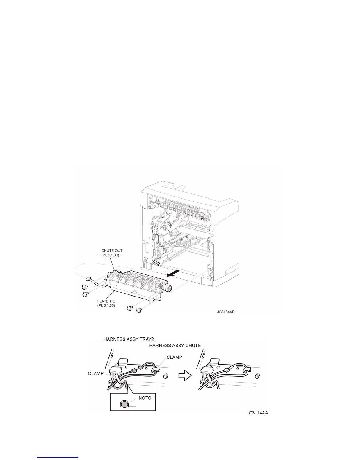
6) Disconnect the connector (P/J248) of the HARNESS ASSEMBLY TRAY 2 (PL 5.1) from the HAR-
NESS ASSEMBLY CHUTE (PL 9.1) (Figure 1).
7) Release the holdings of the harness from 2 clamps on the PLATE TIE (PL 5.1) (Figure 2).
8) Remove the 4 screws (silver with flange, and spring washer 8mm) securing the PLATE TIE to the
frame (Figure 1).
9) Remove the 2 screws (silver with flange, and spring washer 8mm) securing the CHUTE OUT (PL
5.1) to the frame (Figure 1).
10) Remove the 550 FEEDER ASSEMBLY from the frame.
Figure 1. 550 Feeder Assembly
Figure 2. Harness Clamps
Replacement