3 - 137
Chapter 3 Removal and Replacement Procedures (RRPs)
RRP7.15 GATE OCT EXIT (PL 7.1)
Removal
1) Remove the COVER REAR 500 (PL 7.1) (RRP7.9).
2) Remove the COVER REAR (PL 1.1) (RRP1.1).
3) Remove the COVER LEFT (PL 1.1) (RRP1.3).
4) Remove the COVER RIGHT (PL 1.1) (RRP1.2).
5) Remove the COVER EXIT 500 (PL 1.1) (RRP7.1).
6) Remove the 500 EXIT ASSEMBLY (PL 7.1) (RRP7.2).
7) Remove the CHUTE LOW EXIT (PL 7.1) (RRP7.3).
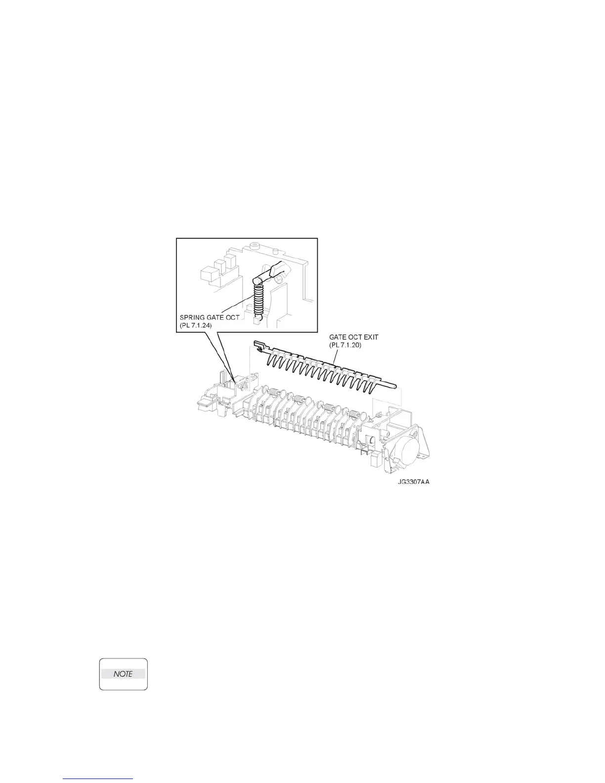
8) Remove the SPRING GATE OCT (PL 7.1) (Figure 1).
9) Bend GATE OCT EXIT (PL 7.1), and remove the it from CHUTE LOW EXIT (Figure 1).
Figure 1. OCT Exit Gate
Replacement
1) Install the GATE OCT EXIT (PL 7.1) (Figure 1).
2) Install the SPRING GATE OCT (PL 7.1) (Figure 1).
3) Install the CHUTE LOW EXIT (PL 7.1) (RRP7.3).
4) Install the 500 EXIT ASSEMBLY (PL 7.1) (RRP7.2).
5) Install the COVER EXIT 500 (PL 1.1) (RRP7.1).
6) Install the COVER RIGHT (PL 1.1) (RRP1.2).
7) Install the COVER LEFT (PL 1.1) (RRP1.3).
8) Install the COVER REAR (PL 1.1) (RRP1.1).
There are 2 kinds of screws, make sure they are installed correctly.
9) Install the COVER REAR 500 (PL 7.1) (RRP7.9).