3 - 114
Chapter 3 Removal and Replacement Procedures (RRPs)
RRP6.12 GUIDE ASSEMBLY CRU R (PL 6.1)
Removal
1) Remove the COVER REAR 500 (PL 7.1) (RRP7.9).
2) Remove the COVER REAR (PL 1.1) (RRP1.1).
3) Remove the FUSER ASSEMBLY (PL 6.1) (RRP6.8).
4) Remove the COVER LEFT (PL 1.1) (RRP1.3).
5) Remove the COVER RIGHT (PL 1.1) (RRP1.2).
6) Remove the COVER EXIT 500 (PL 1.1) (RRP7.1).
7) Remove the 500 EXIT ASSEMBLY (PL 7.1) (RRP7.2).
8) Remove the COVER TOP (PL 1.1) (RRP1.4).
9) Remove the COVER FRONT (PL 1.1) (RRP1.5).
10) Remove the BTR ASSEMBLY (PL 6.1) (RRP6.9).
11) Remove the SHIELD ASSEMBLY ESS (PL 9.1) (RRP9.7).
12) Remove the SHIELD PLATE HVPS (PL 9.1) (RRP9.9)
13) Remove the DUCT FRONT (PL 6.1) (RRP6.2).
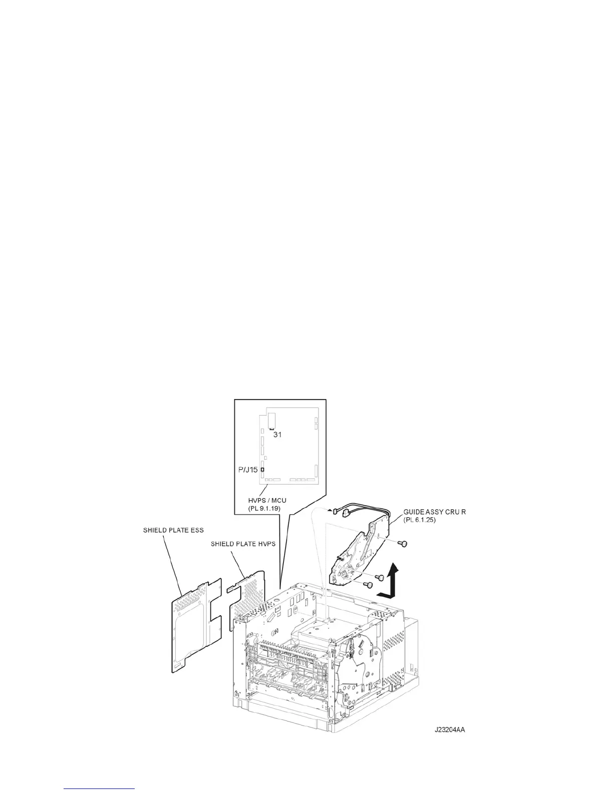
14) Disconnect the connector (P/J31) of the GUIDE ASSEMBLY CRU R from the HVPS/MCU (PL
9.1.19) (Figure 1).
15) Disconnect the connector (P/J15) of the HARNESS ASSEMBLY ANT from the HVPS/MCU (Figure
1).
16) Remove the 3 screws (silver, 6mm) securing the GUIDE ASSEMBLY CRU R to the frame (Figure
1).
17) Pull out the harness of the GUIDE ASSEMBLY CRU R from the frame (Figure 1).
18) Remove the GUIDE ASSEMBLY CRU R.
Figure 1. Right CRU Guide Assembly

 Loading...


