3 - 160
Chapter 3 Removal and Replacement Procedures (RRPs)
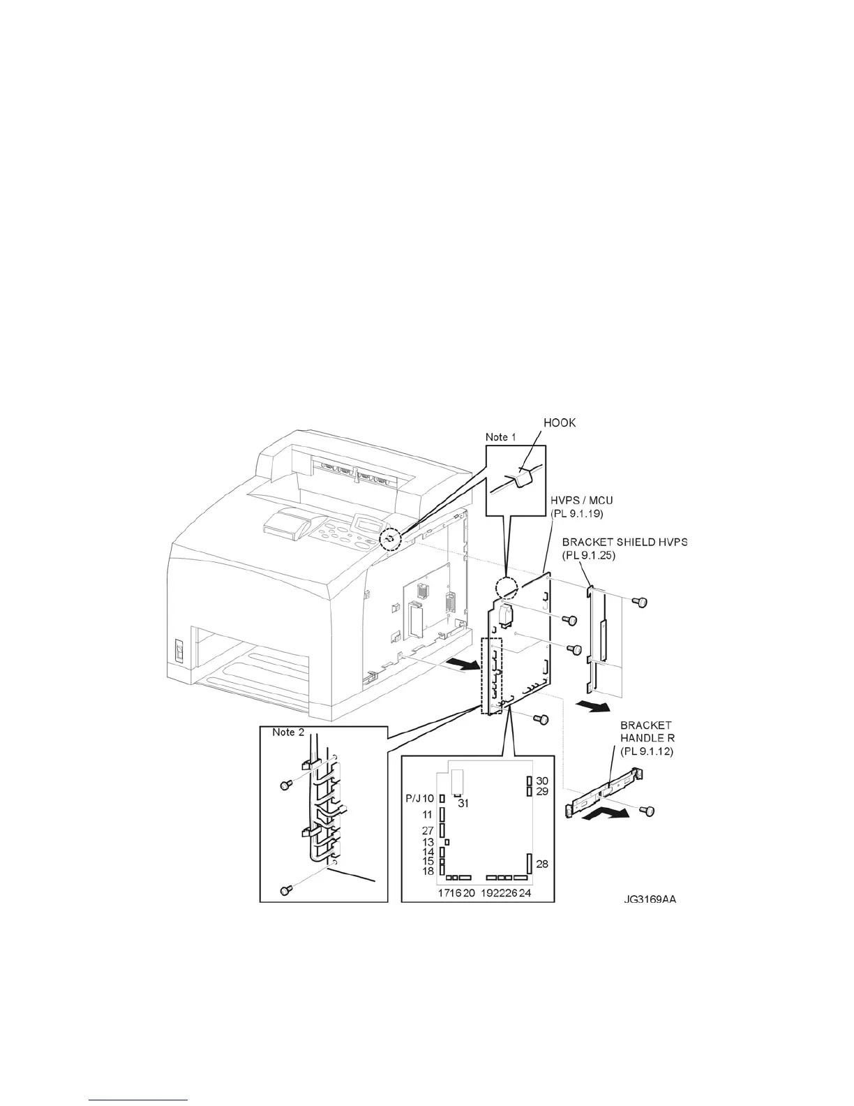
RRP9.10 HVPS/MCU (PL 9.1.19)
Removal
1) Remove the COVER RIGHT (PL 1.1) (RRP1.2).
2) Remove the SHIELD ASSEMBLY ESS (PL 9.1) (RRP9.7).
3) Remove the SHIELD PLATE HVPS (PL 9.1) (RRP9.9).
4) Remove the screw (silver, 6mm) securing the BRACKET HANDLE R (PL 9.1.12) to the frame.
5) Remove the BRACKET HANDLE R from the frame.
6) Disconnect the harness connectors from the connectors (P/J10, P/J11, P/J13, P/J14, P/J15, P/
J16, P/J17, P/J18, P/J20, P/J22, P/J24, P/J26, P/J 27, P/J 28, P/J29, P/J30, and P/J31) on the
HVPS/MCU (Figure 1).
7) Remove the 3 screws (silver, 6mm) securing the BRACKET SHIELD HVPS (PL 9.1) to the frame
(Figure 1).
8) Remove the 4 screws (silver, 6mm) securing the HVPS/MCU (PL 9.1) to the frame (Figure 1).
9) Carefully remove the HVPS/MCU from the 2 mounting tabs on the right side of the frame and slide
the unit down slightly to release it from the frame hook (Figure 1).
Figure 1. HVPS/MCU
Replacement
1) Carefully slide the unit under the frame hook and seat it on the 2 mounting tabs on the right side of
the frame (Figure 1).
2) Replace the 4 screws (silver, 6mm) securing the HVPS/MCU (PL 9.1) to the frame (Figure 1).

 Loading...


