3 - 152
Chapter 3 Removal and Replacement Procedures (RRPs)
RRP9.4 POWER SWITCH (PL 9.1.6), HARNESS ASSEMBLY AC100V/AC200V (PL
9.1.8)
Removal
1) Remove the COVER REAR 500 (PL 7.1) (RRP7.9).
2) Remove the COVER REAR (PL 1.1) (RRP1.1).
3) Remove the COVER LEFT (PL 1.1) (RRP1.3).
4) Remove the COVER RIGHT (PL 1.1) (RRP1.2).
5) Remove the COVER EXIT 500 (PL 1.1) (RRP7.1).
6) Remove the 500 EXIT ASSEMBLY (PL 7.1) (RRP7.2).
7) Remove the COVER TOP (PL 1.1) (RRP1.4).
8) Remove the COVER FRONT (PL 1.1) (RRP1.5).
9) Remove the SHIELD PLATE LVPS (PL 9.1) (RRP8.1).
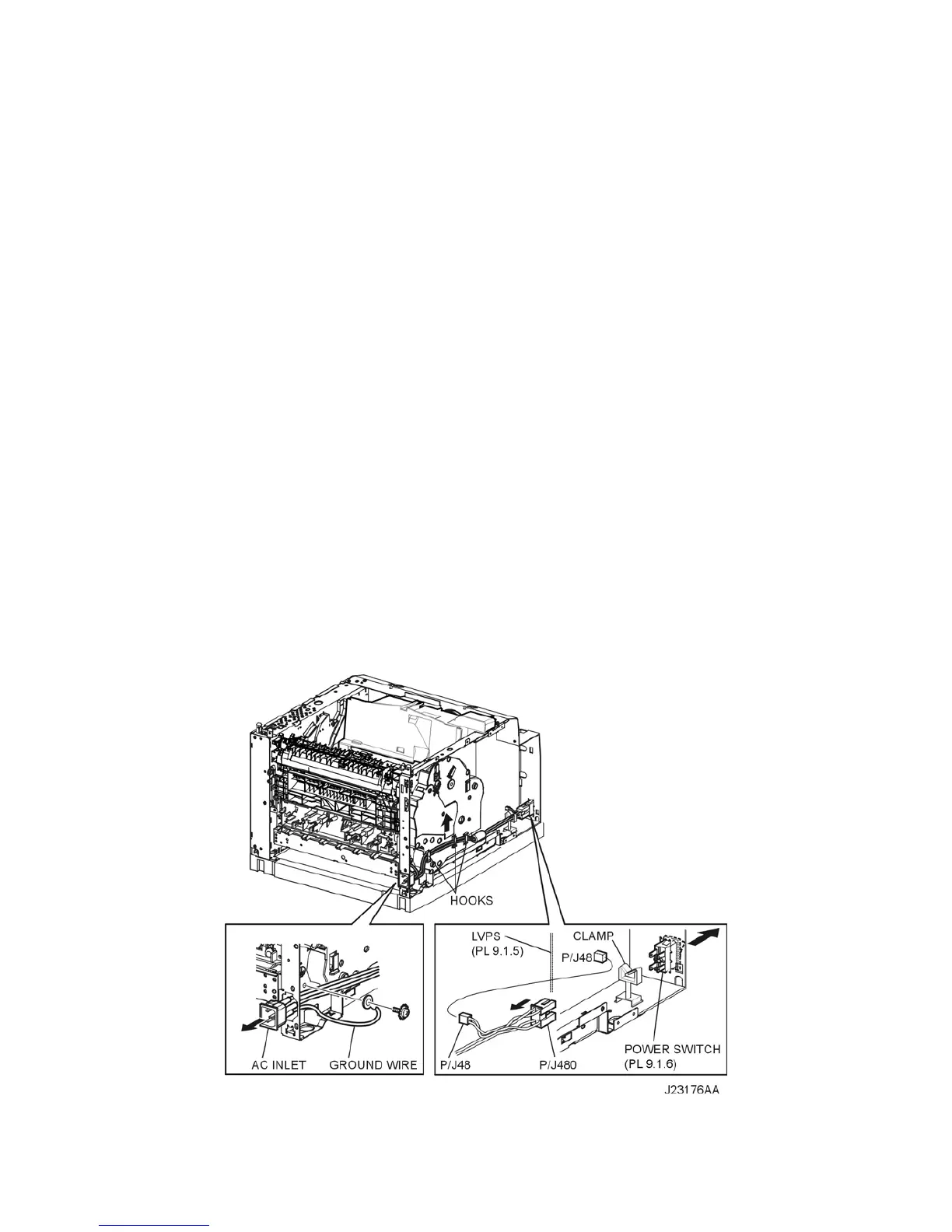
10) Release the clamp of the HARNESS ASSEMBLY AC100V/AC200V from the clamps on the GEAR
ASSEMBLY HOUSING (PL 8.1.3) (Figure 1).
11) Disconnect the connector (P/J480) of the HARNESS ASSEMBLY AC100V/AC200V from the
POWER SWITCH (Figure 1).
12) Disconnect the connector (P/J48) of the HARNESS ASSEMBLY AC100V/AC200V from the LVPS
(PL 9.1.5) (Figure 1).
13) Release the clamp of the HARNESS ASSEMBLY AC100V/AC200V (Figure 1).
14) Remove the screw (silver with toothed washer, 6mm) securing the ground terminal of the HAR-
NESS ASSEMBLY AC100V/AC200V to the frame (Figure 1).
15) Pull out the HARNESS ASSEMBLY AC100V/AC200V from the hole at the rear of the frame (Fig-
ure 1).
16) Remove the POWER SWITCH from the frame.
Figure 1. Power Switch & Harness Assembly