3 - 103
Chapter 3 Removal and Replacement Procedures (RRPs)
RRP6.5 INTERLOCK S/W 24V, INTERLOCK S/W 5V (PL 6.1)
Removal
1) Remove the COVER REAR 500 (PL 7.1) (RRP7.9).
2) Remove the COVER REAR (PL 1.1) (RRP1.1).
3) Remove the FUSER ASSEMBLY (PL 6.1) (RRP6.8).
4) Remove the COVER LEFT (PL 1.1) (RRP1.3).
5) Remove the COVER RIGHT (PL 1.1) (RRP1.2).
6) Remove the COVER EXIT 500 (PL 1.1) (RRP7.1).
7) Remove the 500 EXIT ASSEMBLY (PL 7.1) (RRP7.2).
8) Remove the COVER TOP (PL 1.1) (RRP1.4).
9) Remove the COVER FRONT (PL 1.1) (RRP1.5).
10) Remove the BTR ASSEMBLY (PL 6.1) (RRP6.9).
11) Remove the DUCT FRONT (PL 6.1) (RRP6.2).
12) Remove the ROS ASSEMBLY (PL 6.1) (RRP6.1).
Be careful not to drop or strike the ROS Assembly with any tools or other objects.
13) Remove the SHIELD PLATE ROS (PL 6.1) (RRP6.3).
14) Remove the GUIDE TRAY LEFT (PL 5.1) (RRP5.8).
15) Remove the MOTOR COVER (PL 8.1) (RRP8.1).
16) Remove the SHIELD PLATE LVPS (PL 9.1) (RRP8.1).
17) Remove the GUIDE CRU LEFT (PL 6.1) (RRP6.4).
18) Remove the COVER GUIDE CRU (PL 6.1) and HARNESS ASSEMBLY FUSER (PL 6.1) from the
GUIDE CRU LEFT (RRP6.7).
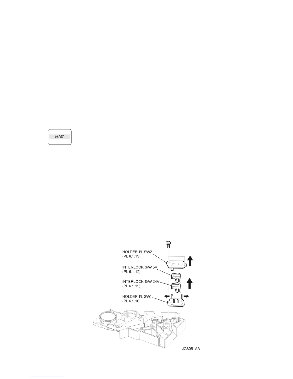
19) Remove the 2 screws (gold tapping, 6mm) securing the HOLDER I/L SW2 (PL 6.1) to the GUIDE
CRU LEFT (Figure 1).
20) Remove the HOLDER I/L SW2 (Figure 1).
21) Release the hook of the HOLDER I/L SW1 (PL 6.1), and remove the INTERLOCK S/W 24V and
INTERLOCK S/W 5V (Figure 1).
Figure 1. 5 Volt & 24 Volt Interlock