3 - 262
Chapter 3 Removal and Replacement Procedures (RRPs)
RRP12.24GUIDE INDICATOR 3 (PL12.3)
Removal
1) Remove the COVER CST (PL 12.3.1) from the 550 PAPER CASSETTE (PL 12.3.50).
2) Remove the HANDLE EXTENSION 550 (PL 12.3.41). (RRP12.23)
When removing the HANDLE EXTENSION 550, the LOW INDICATOR (PL 12.3.37) and
LOW IND FRONT (PL 12.3.38) will be detached. Be careful not to lose them.
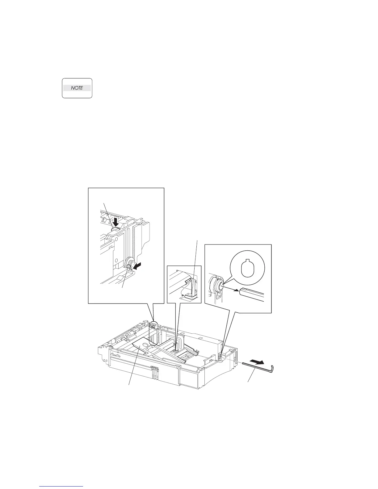
3) While pressing down the lock of the STOPPER GEAR (PL 12.3.29), release the lock of the
LEVER BTM LOCK (PL 12.3.27) and lift up the PLATE ASSY BTM (PL 12.3.10).
4) Remove the link lever of the GUIDE INDICATOR 1 (PL 12.3.34) from the hole of the PLATE
ASSY BTM.
5) While pressing the link lever down to the bottom side of the 550 PAPER CASSETTE, slowly
but firmly draw the GUIDE INDICATOR 3 out from the front side of the HOUSING EXTENSION
550 (PL 12.3.42).
Replacement
1) While pressing the link lever down to the bottom side of the 550 PAPER CASSETTE, insert the
GUIDE INDICATOR 3 to the HOUSING EXTENSION 550 (PL 12.3.42) from the front side.
JG3527AA
GUIDE INDICATOR 3
(PL20.3.36)
GUIDE INDICATOR 1
LEVER BTM LOCK
(PL20.3.27)
STOPPER GEAR
(PL20.3.29)
PLATE ASSY BTM
(PL20.3.10)

 Loading...


