3 - 9
Chapter 3 Removal and Replacement Procedures (RRPs)
RRP1.5 COVER FRONT (PL 1.1)
Removal
1) Remove the COVER REAR 500 (PL 7.1) (RRP7.9)
2) Remove the COVER REAR (PL 1.1) (RRP1.1)
3) Remove the COVER LEFT (PL 1.1) (RRP1.3)
4) Remove the COVER RIGHT (PL 1.1) (RRP1.2)
5) Remove the COVER EXIT 500 (PL 1.1) (RRP7.1)
6) Remove the 500 EXIT ASSEMBLY (PL 7.1) (RRP7.2).
7) Remove the COVER TOP (PL 1.1) (RRP1.4)
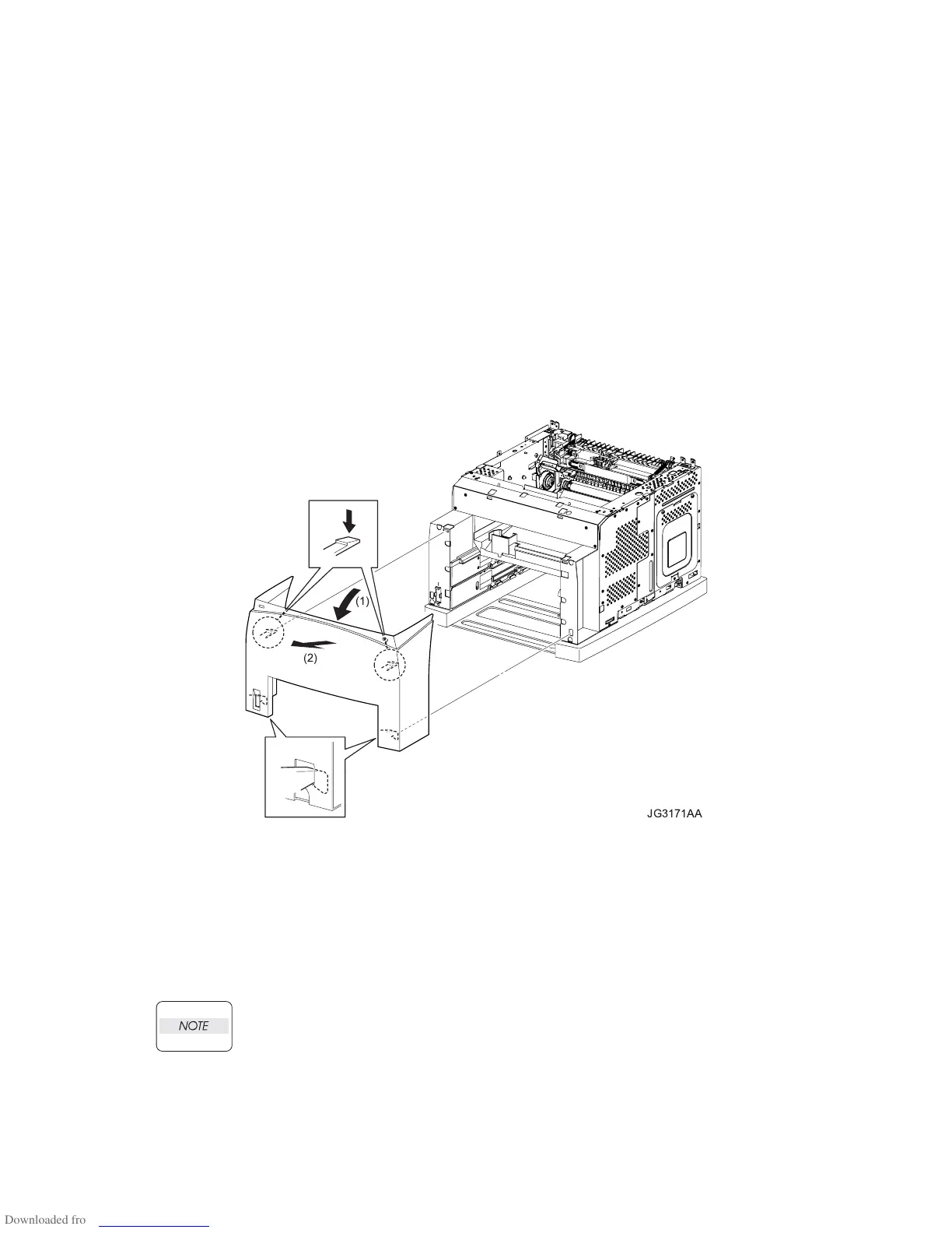
8) Release the 2 hooks of the COVER FRONT securing it to the printer by pressing down the 2 hooks
at the upper portion of the cover, and open it to the front (arrow 1) (Figure 1).
9) Shift the COVER FRONT in the direction of the arrow 2 (Figure 1). Remove the cover from the
printer by releasing the 2 hooks at the lower portion of the cover (Figure 1).
Figure 1. Cover Front
Replacement
1) Hang the 2 hooks at the lower portion of the COVER FRONT to the printer (Figure 1).
2) Lock the 2 hooks at the upper portion of the COVER FRONT to the printer, and secure it to the
printer (Figure 1).
3) Install the COVER TOP (PL 1.1) (RRP1.4).
4) Install the 500 EXIT ASSEMBLY (PL 7.1) (RRP7.2).
When installing, put the harnesses of the MOTOR ASSEMBLY EXIT and HARNESS
ASSEMBLY EXIT SNR1 into the square hole of the frame.
5) Install the COVER EXIT 500 (PL 1.1) (RRP7.1).
6) Install the COVER RIGHT (PL 1.1) (RRP1.2).
7) Install the COVER LEFT (PL 1.1) (RRP1.3).
8) Install the COVER REAR (PL 1.1) (RRP1.1).
9) Install the COVER REAR 500 (PL 7.1) (RRP7.9).
JG3171AA
(1)
(2)

 Loading...


