3 - 149
Chapter 3 Removal and Replacement Procedures (RRPs)
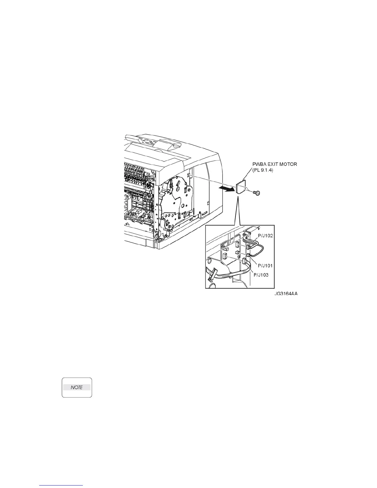
RRP9.2 PWBA EXIT MOTOR (PL 9.1.4)
Removal
1) Remove the COVER REAR 500 (PL 7.1) (RRP7.9).
2) Remove the COVER REAR (PL 1.1) (RRP1.1).
3) Remove the COVER LEFT (PL 1.1) (RRP1.3).
4) Disconnect the harnesses from the connectors (P/J101, P/J102 and P/J103) on the PWBA EXIT
MOTOR (Figure 1).
5) Remove the 2 screws (silver, 6mm) securing the PWBA EXIT MOTOR to the frame (Figure 1).
6) Remove the PWBA EXIT MOTOR (Figure 1).
Figure 1. Exit Motor PWBA
Replacement
1) Install the PWBA EXIT MOTOR to the frame using the 2 screws (silver, 6mm) (Figure 1).
2) Connect the harness connectors to the connectors (P/J101, P/J102 and P/J103) on the PWBA
EXIT MOTOR (Figure 1).
3) Install the COVER LEFT (PL 1.1) (RRP1.3).
4) Install the COVER REAR (PL 1.1) (RRP1.1).
There are 2 kinds of screws, make sure they are installed correctly.
5) Install the COVER REAR 500 (PL 7.1) (RRP7.9).

 Loading...


