3 - 120
Chapter 3 Removal and Replacement Procedures (RRPs)
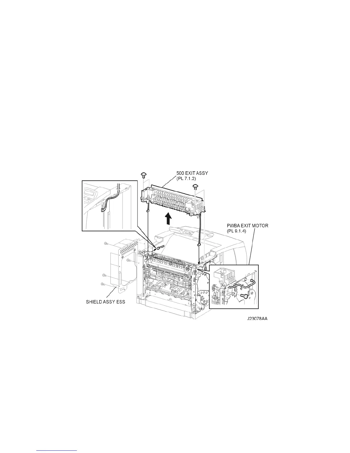
RRP7.2 500 EXIT ASSEMBLY
Removal
1) Remove the COVER REAR 500 (PL 7.1) (RRP7.9).
2) Remove the COVER REAR (PL 1.1) (RRP1.1).
3) Remove the COVER LEFT (PL 1.1) (RRP1.3).
4) Remove the COVER RIGHT (PL 1.1) (RRP1.2).
5) Remove the COVER EXIT 500 (PL 1.1) (RRP7.1).
6) Remove the SHIELD ASSEMBLY ESS (PL 9.1) (RRP9.7)
7) Disconnect the connector (P/J29) of the HARNESS ASSEMBLY EXIT SNR from the HVPS/MCU
(PL 9.1.19) (Figure 1).
8) Disconnect the connector (P/J103) of the MOTOR ASSEMBLY EXIT from the PWBA EXIT
MOTOR (PL 9.1.4) (Figure 1).
9) Remove the 5 screws (gold with spring washer,10mm,x4,silver 6mm,x1)securing the 500 EXIT
ASSEMBLY to the printer (Figure 1).
10) Remove the 500 EXIT ASSEMBLY.
Figure 1. 500 Exit Assembly
Replacement
1) Put the harnesses of the MOTOR ASSEMBLY EXIT and SENSOR into the hole on the frame (Fig-
ure 1).
2) Install the 500 EXIT ASSEMBLY using the 5 screws (gold with spring washer,10mm,x4,silver
6mm,x1) (Figure 1).
3) Connect the connector (P/J103) of the MOTOR ASSEMBLY EXIT to the PWBA EXIT MOTOR (PL
9.1.4) (Figure 1).
4) Connect the connector (P/J29) of the HARNESS ASSEMBLY EXIT SNR to the HVPS/MCU (PL
9.1.19) (Figure 1).
5) Install the SHIELD ASSEMBLY ESS (PL 9.1) (RRP9.7).
6) Install the COVER EXIT 500 (PL 1.1) (RRP7.1).

 Loading...


