3 - 126
Chapter 3 Removal and Replacement Procedures (RRPs)
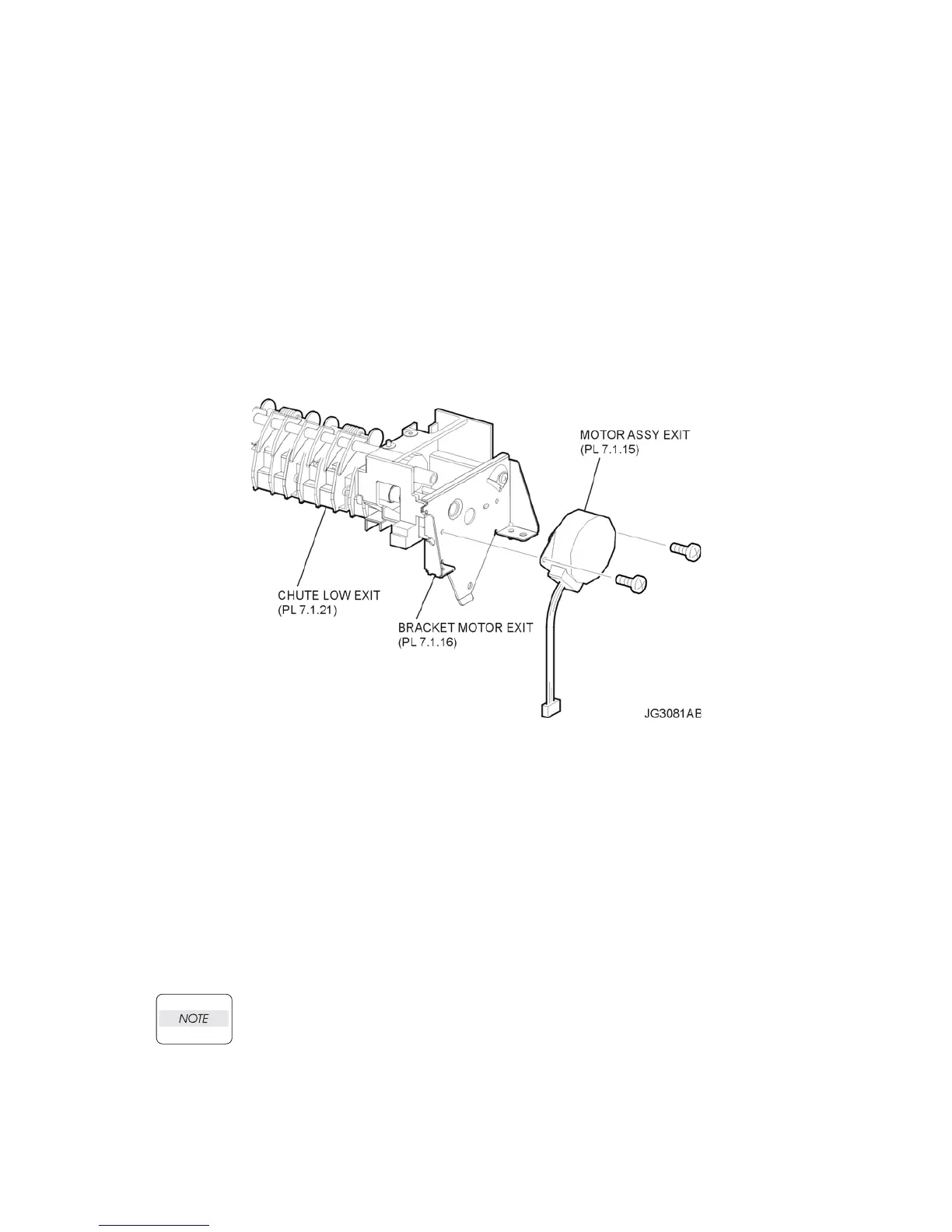
RRP7.5 MOTOR ASSEMBLY EXIT (PL 7.1.15)
Removal
1) Remove the COVER REAR 500 (PL 7.1) (RRP7.9).
2) Remove the COVER REAR (PL 1.1) (RRP1.1).
3) Remove the COVER LEFT (PL 1.1) (RRP1.3).
4) Remove the COVER RIGHT (PL 1.1) (RRP1.2).
5) Remove the COVER EXIT 500 (PL 1.1) (RRP7.1).
6) Remove the 500 EXIT ASSEMBLY (PL 7.1) (RRP7.2).
7) Remove the CHUTE LOW EXIT (PL 7.11) (RRP7.3).
8) Remove the 2 screws (silver, 6mm) securing the MOTOR ASSEMBLY EXIT to the BRACKET
MOTOR EXIT (PL 7.1) (Figure 1).
9) Remove the MOTOR ASSEMBLY EXIT (Figure 1).
Figure 1. Exit Motor Assembly
Replacement
1) Secure the MOTOR ASSEMBLY EXIT to the BRACKET MOTOR EXIT (PL 7.1) using the 2
screws (silver, 8mm) (Figure 1).
2) Install the CHUTE LOW EXIT (PL 7.11) (RRP7.3).
3) Install the 500 EXIT ASSEMBLY (PL 7.1) (RRP7.2).
4) Install the COVER EXIT 500 (PL 1.1) (RRP7.1).
5) Install the COVER RIGHT (PL 1.1) (RRP1.2).
6) Install the COVER LEFT (PL 1.1) (RRP1.3).
7) Install the COVER REAR (PL 1.1) (RRP1.1).
There are 2 kinds of screws, make sure they are installed correctly.
8) Install the COVER REAR 500 (PL 7.1) (RRP7.9).