3 - 218
Chapter 3 Removal and Replacement Procedures (RRPs)
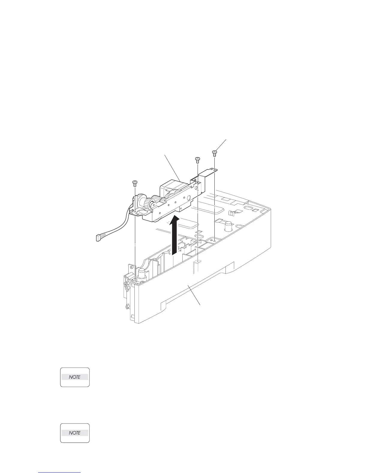
RRP12.5 DRIVE ASSY OPT FDR (PL12.1)
Removal
1) Remove the 550 FEEDER OPTION (PL 12.2). (RRP12.1)
2) Remove the COVER LEFT PLATE (PL 12.1.3). (RRP12.3)
3) Disconnect the connector (P/J820) of the MOTOR FEEDER (PL 12.1.17) attached to the
DRIVE ASSY OPT FDR from the HARNESS ASSY FDR MOT (PL 12.1.37).
4) Remove the 3 screws (gold tapping, 8mm x 2, silver, 6mm x 1) securing the DRIVE ASSY OPT
FDR to the FRAME CVR L550 (PL 12.1).
5) Remove the DRIVE ASSY OPT FDR.
Replacement
1) Install the DRIVE ASSY OPT FDR to the FRAME CVR L550 (PL 12.1) using the 3 screws (gold
tapping, 8mm x 2, silver, 8mm x 1).
Be sure to tighten the screw (silver, 6mm) shown as Screw (A) in the figure. When tight-
ening the screws, be careful not to pinch the harness between the board and frame.
2) Connect the connector (P/J820) of the MOTOR FEEDER (PL 12.1.17) attached to the DRIVE
ASSY OPT FDR to the HARNESS ASSY FDR MOT (PL 12.1.37).
3) Install the COVER LEFT PLATE (PL 12.1.3). (RRP12.3)
When installing the EARTH PLATE, be sure to install the tip of the EARTH PLATE under
the COVER LEFT PLATE.
DRIVE ASSY OPT FDR
(PL20.1.8)
J23506AA
FRAME CVR L550
(PL20.1.21)
Screw(A)

 Loading...


