3 - 42
Chapter 3 Removal and Replacement Procedures (RRPs)
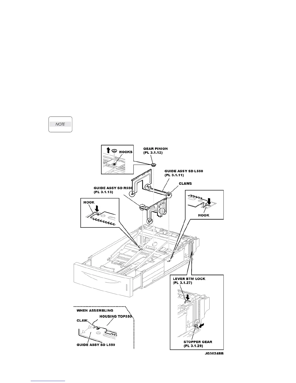
RRP3.5 PLATE ASSEMBLY BTM
Removal
1) Remove the COVER CST (PL 12.3) from the 550 PAPER CASSETTE.
2) Release the lock of the LOCK EXTENSION, and pull out the cassette extension as far as it will go.
3) Release the hooks securing the GEAR PINION (PL 12.3) to the HOUSING TOP 550 (PL 12.3),
and remove the GEAR PINION (Figure 1).
4) While pressing down the lock of the STOPPER GEAR (PL 12.3), release the lock of the LEVER
BTM LOCK (PL 3.1) to lift up the PLATE ASSEMBLY BTM (Figure 1).
5) Slide the GUIDE ASSEMBLY SD L550 (PL 12.3) inward, and remove it from the HOUSING TOP
550 by pressing down the hook of the HOUSING TOP 550.
6) Slide the GUIDE ASSEMBLY SD R550 (PL 12.3) inward, and remove it from the HOUSING TOP
550 by pressing down the hook of the HOUSING TOP 550
In the following steps, the GEAR PB L (PL 3.1), GEAR BTM DMP ONEWAY (PL 3.1) and
GEAR BTM LOCK ONEWAY (PL 3.1) will be detached (Figure 2). Be careful not to lose
these gears.
.
Figure 1. Plate Assembly BTM
NOTE 3

 Loading...


