3 - 40
Chapter 3 Removal and Replacement Procedures (RRPs)
8) Release the 4 hooks of the HOUSING TOP 550, and remove the HOUSING TOP 550 together
with the HOUSING EXTENSION 550 (PL 3.1) from the HOUSING BASE 550.
9) Remove the 4 screws (gold tapping, 6mm) securing the COVER EXTENSION (PL 3.1) to the
HOUSING EXTENSION 550.
10) Remove the COVER EXTENSION from the HOUSING EXTENSION 550.
11) Remove the RACK SIZE (PL 3.1) (RRP3.2)
12) Remove the GEAR SECTOR (PL 3.1) (RRP3.3).
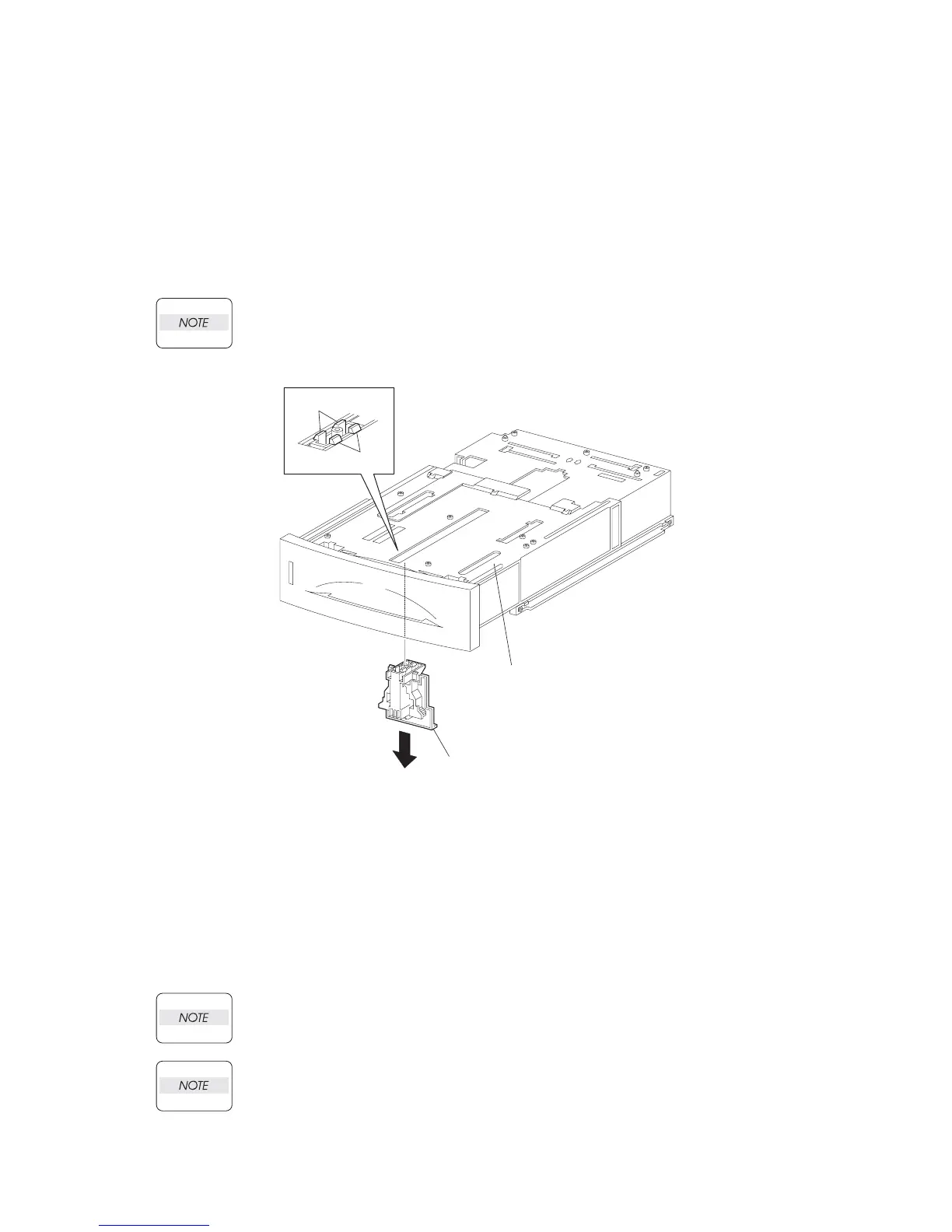
13) Release the hooks securing the GUIDE ASSEMBLY END 550 to the HOUSING EXTENSION 550
(PL 3.1) (Figure 2).
Be careful handling the hooks of the GUIDE ASSEMBLY END 550. They are fragile and
could break if given excessive force.
14) Remove the GUIDE ASSEMBLY END 550 from the HOUSING EXTENSION 550.
Figure 2. Guide Assembly End 550
Replacement
1) Secure the GUIDE ASSEMBLY END 550 to the HOUSING EXTENSION 550 (PL 3.1) using the 4
hooks.
2) Install the GEAR SECTOR (PL 3.1) (RRP3.3)
3) Install the RACK SIZE (PL 3.1) (RRP3.2)
4) Install the COVER EXTENSION (PL 3.1) to the HOUSING EXTENSION 550 using the four screws
(gold tapping, 6mm).
When installing, make sure the COVER EXTENSION is inserted under 3 claws of the
HOUSING EXTENSION 550.
Use 6mm size of fixed screw. If 8mm size of screw is used, HOUSING EXTENSION 550
doesn't operate smoothly and LOCK EXTENSION 550 doesn't operate correctly.
HOOKS
HOOKS
GUIDE ASSY END 550
(PL4.1.43)
HOUSING EXTENSION 550
(PL4.1.42)
JG3023AA
(PL 3.1.43)
(PL 3.1)

 Loading...


