3 - 265
Chapter 3 Removal and Replacement Procedures (RRPs)
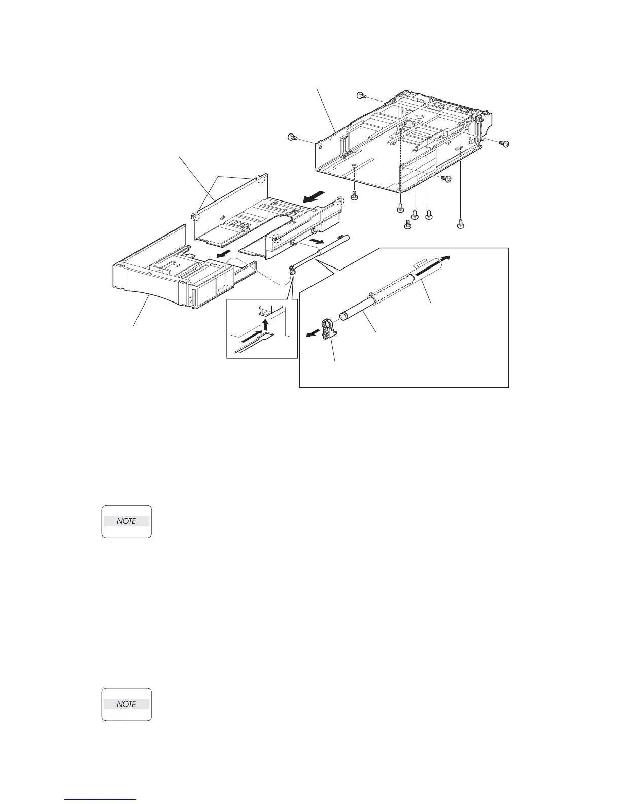
Replacement
1) Insert the GUIDE INDICATOR 2 into the hole of the GUIDE INDICATOR 1 (PL 12.3.34) from
back.
2) Install the SUPPORT GUIDE IND (PL 12.3.32) to the GUIDE INDICATOR2, and secure it with
the hook.
Install the SUPPORT GUIDE IND to the GUIDE INDICATOR 2 in the direction shown in
the figure.
3) Install the SUPPORT GUIDE IND together with the GUIDE INDICATOR 1 and GUIDE INDICA-
TOR 2 to the HOUSING TOP 550 (PL 12.3.16), and secure the GUIDE INDICATOR 1 using
the 2 hooks of the HOUSING TOP 550.
4) Slide the SUPPORT GUIDE IND along the groove of the HOUSING EXTENSION 550 to
install, and assemble the HOUSING TOP 550 and HOUSING EXTENSION 550 into 1 unit.
5) Install the HOUSING EXTENSION 550 and HOUSING TOP 550 (PL 12.3.16) to the HOUSING
BASE 550 while pushing the LINK SW SIZE1-550 (PL 12.3.45), LINK SW SIZE2-550 (PL
12.3.46) and LINK SW SIZE3-550 (PL 12.3.47) of the HOUSING BASE 550 outward as shown
in the figure.( Figure 20.18)
Be sure to put 2 claws at the tip of the PLATE ASSY BTM under the hooks on the HOUS-
ING TOP 550.
6)After assembling the HOUSING TOP 550 with HOUSING BASE 550 using the 4 hooks,
secure them using the 2 screws (gold tapping, 8mm) from both right and left sides, as well as
the 6 screws (gold tapping, 8mm) on back.
JG3528AA
GUIDE INDICATOR 1
(PL20.3.34)
GUIDE INDICATOR 2
(PL20.3.35)
SUPPORT GUIDE IND
(PL20.3.32)
HOUSING EXTENSION 550
HOUSING TOP 550
HOUSING BASE 550
HOOKS
 Loading...


