6 – 20
Chapter 6 Principles of Operation
ROS ASSY
The ROS (Raster Output Scanner) scans the surface of the drum with a laser
beam. The ROS ASSY consists of the following three components, i.e., LD (Laser
Diode) Assembly, Scanner Assembly, and SOS PWB.
-LD Assembly
The LD Assembly produces a laser beam. This beam is turned ON and OFF according to a
print data signal.
-Scanner Assembly
The Scanner Assembly consists of a Polygon Mirror (12 facets) and a Scanner Motor. The
Polygon Mirror is mounted to the shaft of the Scanner Motor. The Scanner Motor rotates the
Polygon Mirror at a specified speed. The rotating Polygon Mirror reflects the beam to the
drum surface through lenses and mirrors, to scan the beam from one end to the other of the
drum. One scan is made with one facet of the mirror. The Scanner Motor is driven by three
phase, full-wave current linear drive. The current through the winding of each phase is
switched by a Hall amplifier matrix. The signal from the phase detection terminal of the Motor
is used.
-SOS PWB
When the laser beam hits the SOS Sensor of the SOS PWB, the beam is converted into an
electrical signal (SOS signal), and the initial position where a scan is started on each line is
detected.
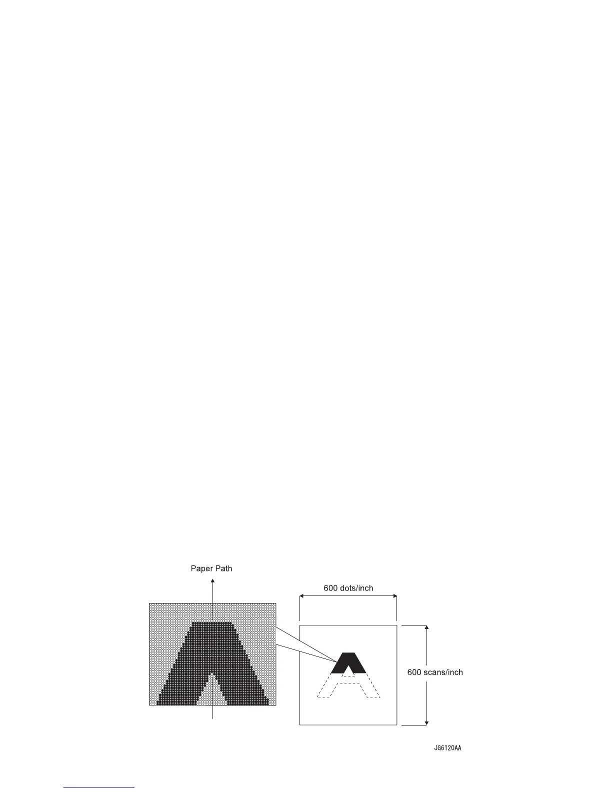
When the laser beam is scanned across the drum surface from one end to the other
while turning ON and OFF the beam, one line of latent image is created. If the
scanning by the laser beam is repeated while rotating the drum, a two-dimensional
image is created. The resolution in the scanning direction (from right to left) is
determined by the rotational speed of the Scanner Motor and by the speed at which
the laser is adjusted. The resolution in the process direction (from top to bottom) is
determined by the rotational speed of the Scanner Motor. (If the scanning speed is
increased, the next row to be scanned can be started earlier accordingly.)
Conceptual diagram of image creation by scanning
Conceptual diagram of image creation by scanning

 Loading...


