I/O module (optional expansion module)
— English Variomat Touch — 09.09.2022-Rev. C
1 1 0 0 0 1 0 0 0 1
2 0 1 0 0 1 0 0 0 2
3 1 1 0 0 1 0 0 0 3
4 0 0 1 0 1 0 0 0 4
5 1 0 1 0 1 0 0 0 5
6 0 1 1 0 1 0 0 0 6
7 1 1 1 0 1 0 0 0 7
8 0 0 0 1 1 0 0 0 8
9 1 0 0 1 1 0 0 0 9
10 0 1 0 1 1 0 0 0 10
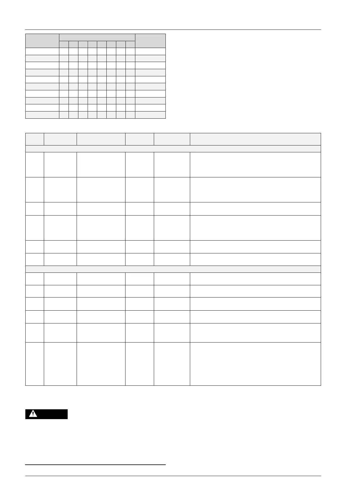
5.2.3 I/O module default settings
The inputs and outputs of the I/O module each have default settings.
These default settings can be changed, if required, and adjusted to local
conditions.
Responses by the inputs 1 – 6 of the I/O module are recorded and displayed in
the device controller's fault memory.
Default settings apply to software version V1.10 and higher.
All digital inputs and outputs can be set freely as option. The
setting is carried out by Reflex Customer Service, 13.1 "Reflex
Customer Service", 49
Signal on the input triggers the following action
1
Normally closed
contact
External temperature
monitoring
Yes Yes • Solenoid valves are closed.
• Solenoid valve (2) in overflow pipe (1)
• Solenoid valve (3) in overflow pipe (2)
• Output relay (1) is switched.
2
Normally closed
contact
External signal, Minimum
pressure
Yes No • Solenoid valves are closed.
• Solenoid valve (2) in overflow pipe (1)
• Solenoid valve (3) in overflow pipe (2)
• Output relay (2) is switched.
3
Normally closed
contact
Manual make-up Yes Yes • Solenoid valve (1) in make-up line is manually opened.
• Output relay (5) is switched.
4
Normally open
contact
Emergency-Off Yes Yes • Pumps (1) and (2) are switched off.
• Solenoid valves (2) and (3) in the overflow pipes are closed.
• Solenoid valve (1) in the make-up line is closed.
• Switches "Group fault" in the device controller.
5
Normally open
contact
Manual pump 1 Yes Yes • Pump (1) is manually switched on.
• Output relay (5) is switched.
6
Normally open
contact
Manual OF-1 Yes Yes Solenoid valve (1) is opened.
1
Changeover
contact
--- --- --- See input 1
2
Changeover
contact
--- --- --- See input 2
3
Changeover
contact
--- --- --- • Below minimum pressure.
• "ER 01" message in the controller
4
Changeover
contact
--- --- --- • Maximum pressure exceeded
• "ER 10" message in the controller
5
Changeover
contact
--- --- --- Switches in manual mode
Switches in stop mode
Switches with inputs 3,5,6 active
6
Changeover
contact
Make-up fault --- --- • Make-up setting values exceeded.
• Switches the following messages in the device controller:
• "ER 06", Make-up time
• "ER 07", Make-up cycles
• "ER 11", Make-up quantity
• "ER 15", Make-up valve
• "ER 20", Maximum make-up quantity
5.3 Replacing the fuses
Risk of serious injury or death due to electric shock. Some parts of the main
board may still carry 230 V voltage even with the device physically isolated
from the 230 V power supply.
• Before you remove the covers, completely isolate the device controller
from the power supply.
• Verify that the main circuit board is voltage-free.
Fusing is provided on the I/O module's main circuit board.
 Loading...
